3D Printing
This section provides essential guidance for producing BonicBot A2 structural components using a 3D printer. It is intended for users printing their own parts as part of the Basic Kit workflow and defines the baseline standards required to achieve mechanically reliable components.
BonicBot A2 parts are designed for FDM 3D printing and require precision focused fabrication rather than aesthetic oriented printing. Each component contributes directly to the robot’s structural stability, alignment accuracy, and motion consistency. Inaccurate or low quality prints may lead to assembly difficulties, mechanical stress, or reduced operational lifespan.
Download STL Files
All required STL files for printing BonicBot A2 components are available for download:
General Print Facts
The following values represent typical requirements for printing the complete BonicBot A2 body structure:
- Estimated total print time: 7 days
- Approximate material usage: 4 to 5 kg
- Recommended material: PLA
Actual values may vary depending on printer calibration, slicing configuration, and material profile.
Tested 3D Printers
The following printers have been officially tested and validated for BonicBot A2 part production:
| Printer Model | Performance Level | Notes |
|---|---|---|
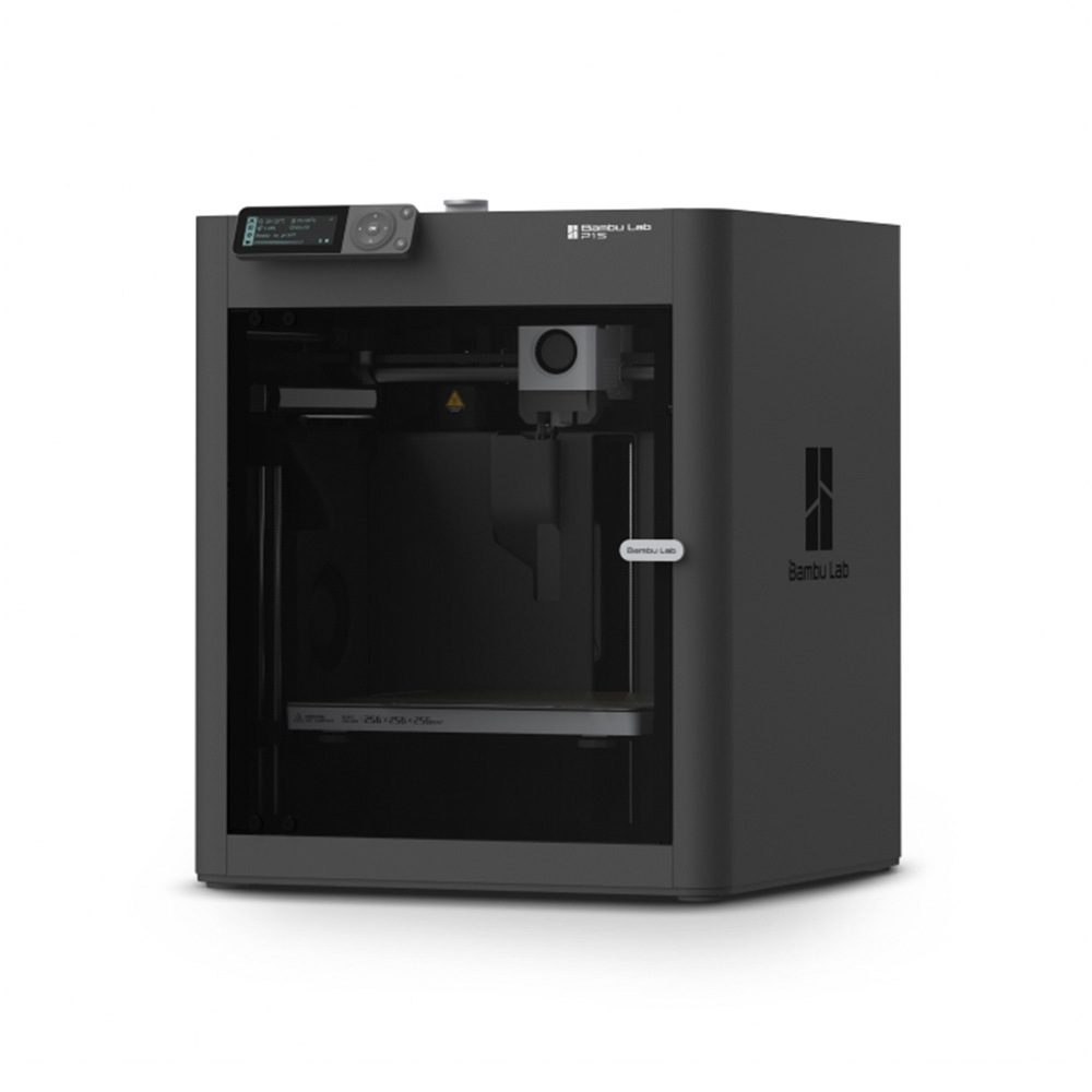
| Bambu Lab P1S | Very High | Consistent precision and high structural quality |
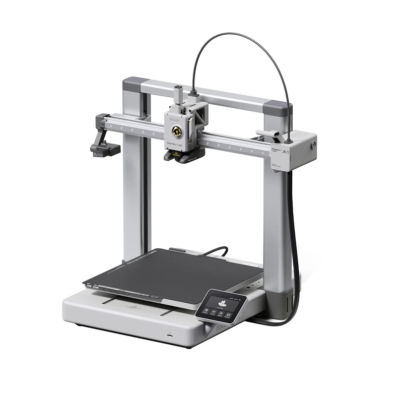
| Bambu Lab A1 | Very High | Optimised for ease of use and repeatability |
Use of these models is strongly recommended to ensure dimensional accuracy and long term durability of printed components.
Tested Printer Visual References
Low grade or brittle filament must be avoided, as it may compromise joint integrity and mechanical reliability.
Orientation Awareness
Each BonicBot A2 component must be printed only in the recommended orientation as shown in the provided reference photos. This orientation has been specifically engineered to achieve optimal mechanical performance and structural reliability.
Correct orientation ensures:
- Stronger load bearing capacity
- Improved layer adhesion
- Reduced structural weakness points
- Accurate alignment during assembly
Deviation from the recommended orientation may negatively affect performance and part durability.
Recommended Slicer Settings and Support Guidance
This subsection outlines the baseline slicer configuration to ensure consistent, mechanically reliable prints while remaining accessible for first-time and non-technical users. Only essential parameters are defined, and validated default presets are preserved.
For Bambu Studio Users
- Preset Profile: 0.16 mm Optimal @ BBL A1
- All other values must remain at their default preset configuration unless explicitly instructed.
For Non Bambu Slicer Users
Configure the following parameters to match the reference images provided:
- Layer Height: 0.16 mm
- Initial Layer Height: 0.20 mm
- Default Line Width: 0.42 mm
- Initial Layer Line Width: 0.50 mm
- Infill: 15 percent grid or gyroid (minimum requirement)
Higher infill may be used if additional mechanical strength is desired.
All remaining parameters must remain at slicer default values suitable for PLA based structural parts.
Support Settings (Applies to All Users)
Supports must follow the default behaviour shown in the reference images.
| Parameter | Value |
|---|---|
| Supports | Enabled |
| Type | Tree (Auto) |
| Style | Default |
| Threshold Angle | 25° |
| Remove Small Overhangs | Enabled |
| On Build Plate Only | Disabled |
| Top Z Distance (Support Interface) | 0.25 mm Recommended |
Critical Practice – Nut Insertion Zones
For parts containing embedded nuts or threaded inserts, users must apply Support Blocking Paint to prevent supports from forming inside nut cavities. This ensures clean seating and prevents mechanical obstruction during assembly.
Failure to follow this practice may result in improper fastening, increased stress points, or permanent damage during installation.
Application Scope
The above slicer and support settings constitute the default standard for all BonicBot A2 components and must be strictly adhered to unless a specific part explicitly defines alternative requirements within its individual part specification.
Reference Resources
- Support Configuration Guide: https://wiki.bambulab.com/en/software/bambu-studio/support
- Support Painting Guide: https://wiki.bambulab.com/en/software/bambu-studio/support-painting