Base Assembly
Step 1: Collecting All Required Parts
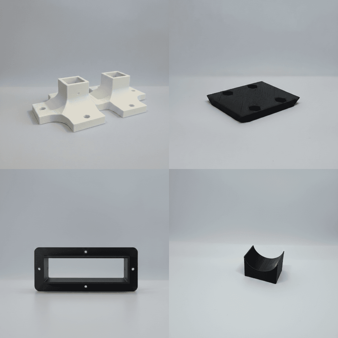
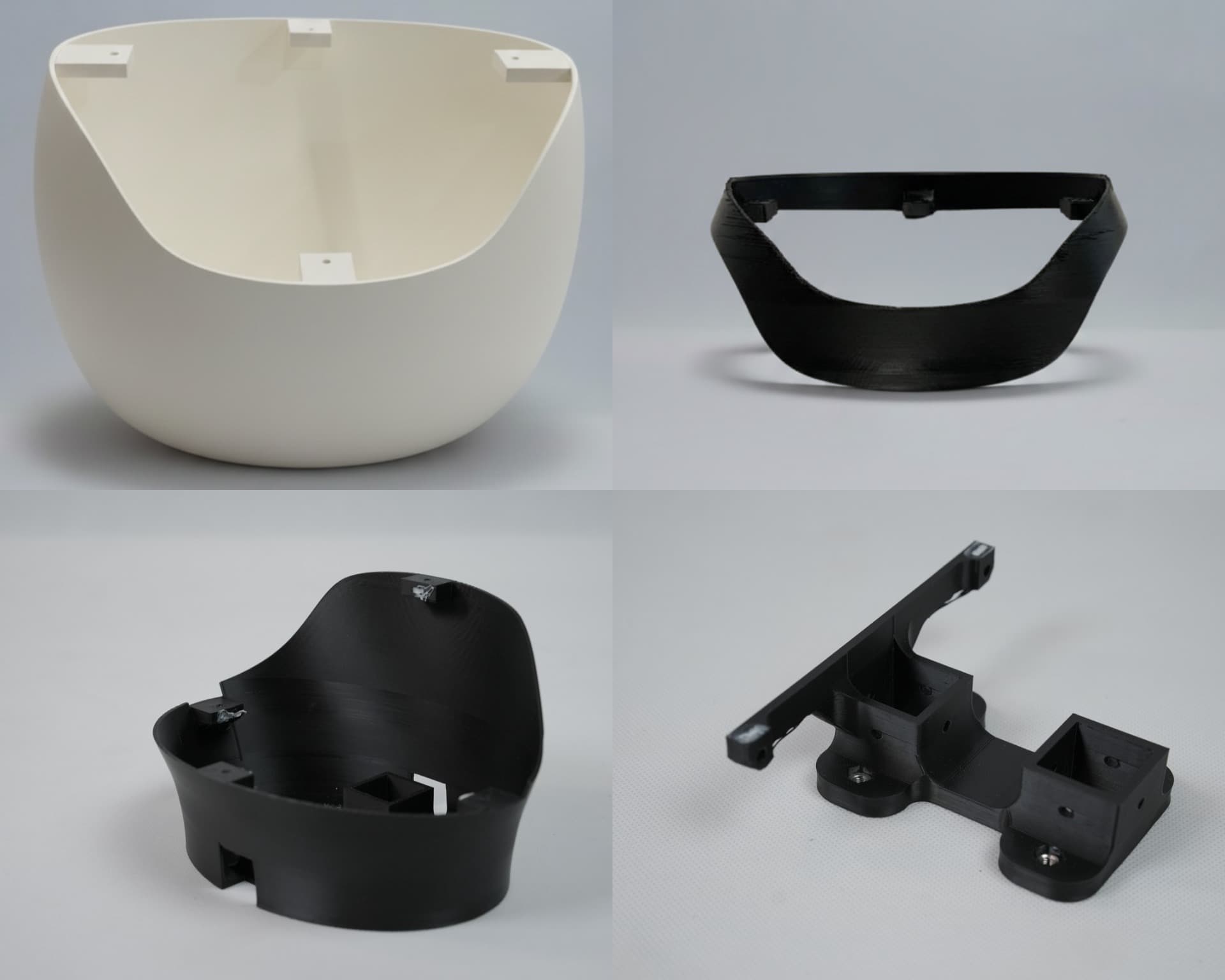
3D Printed Parts
Base Rear Left, Base Rear Right, Base Front Left, Base Front Right, Base Center Cover, Battery Holder
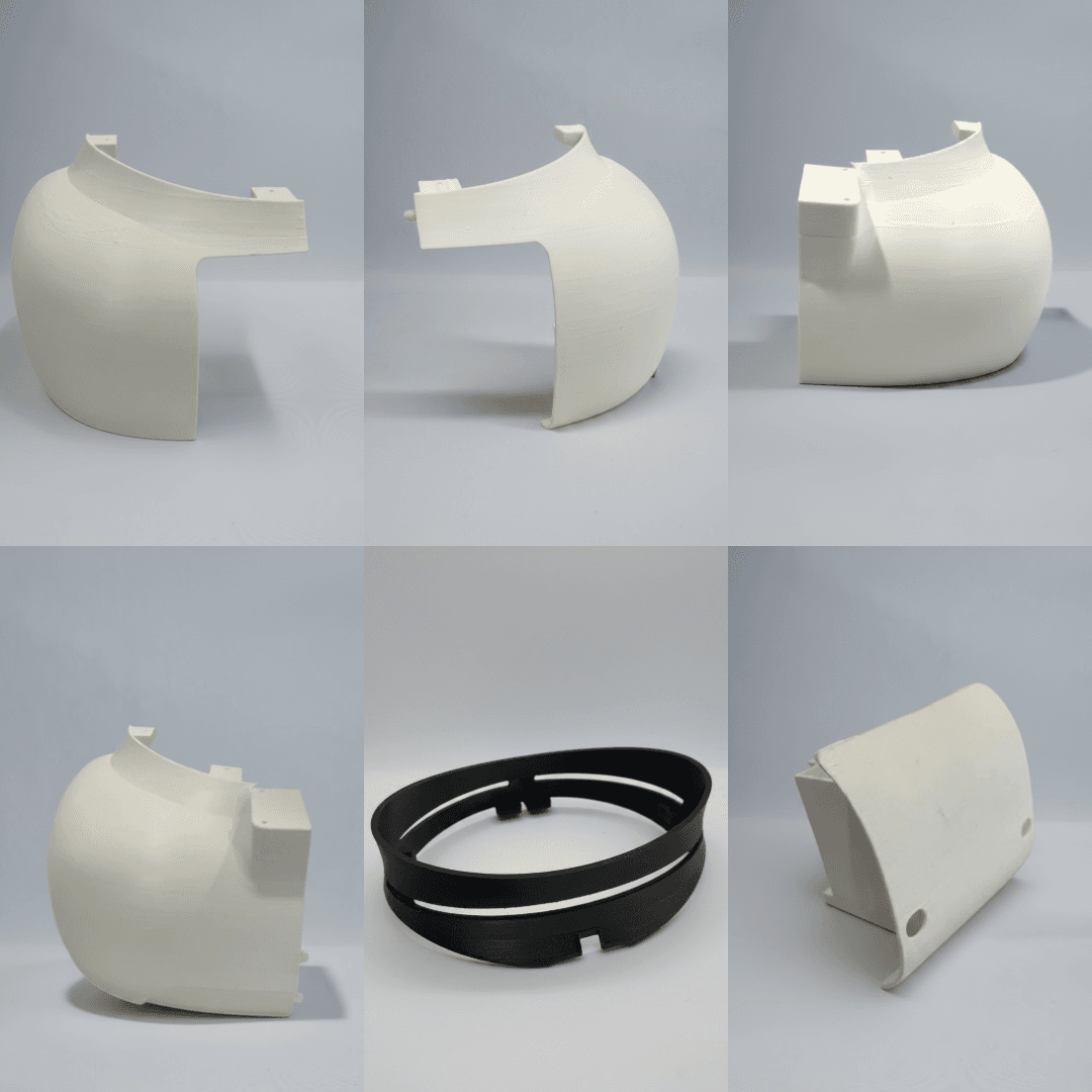
Base Joint, Battery Rail, BCC Acrylic Holder, Motor Stabilizer
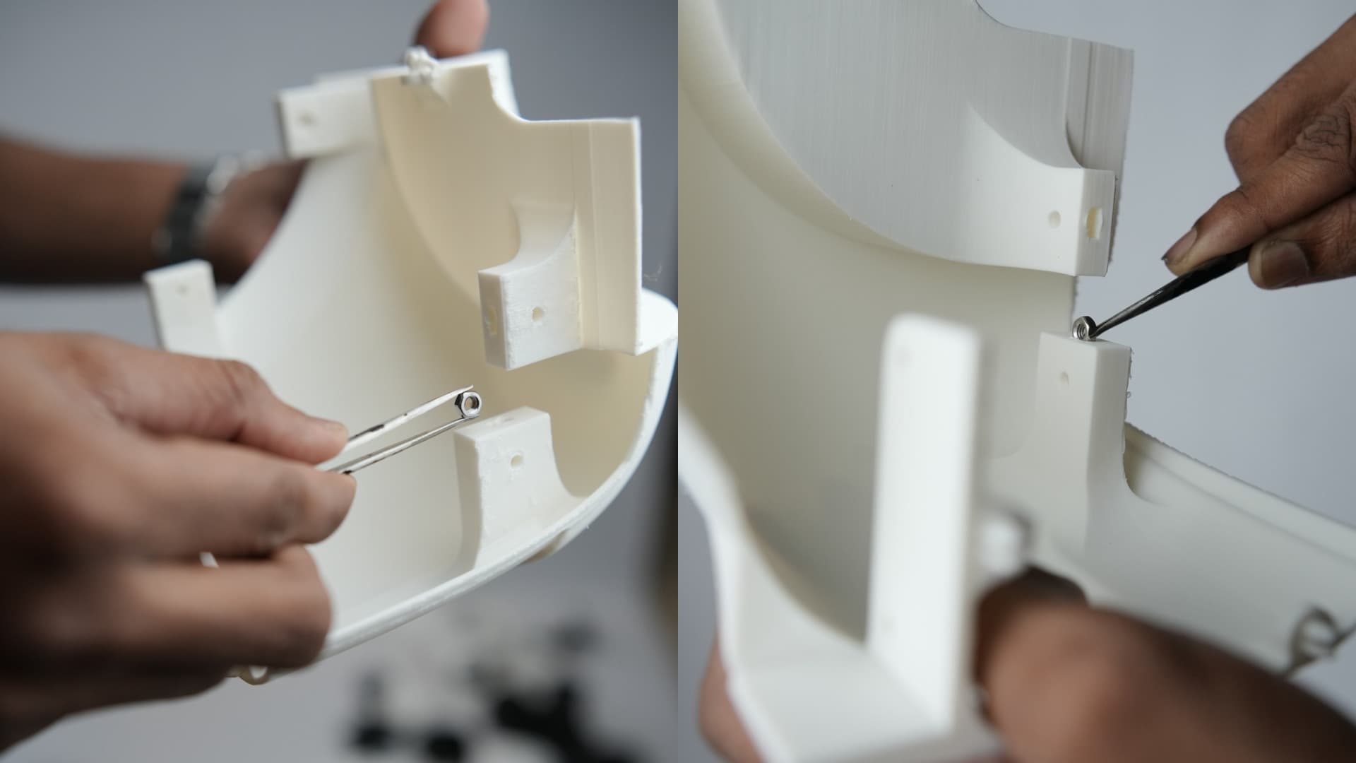
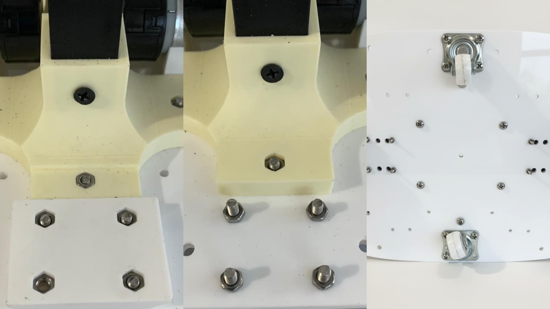
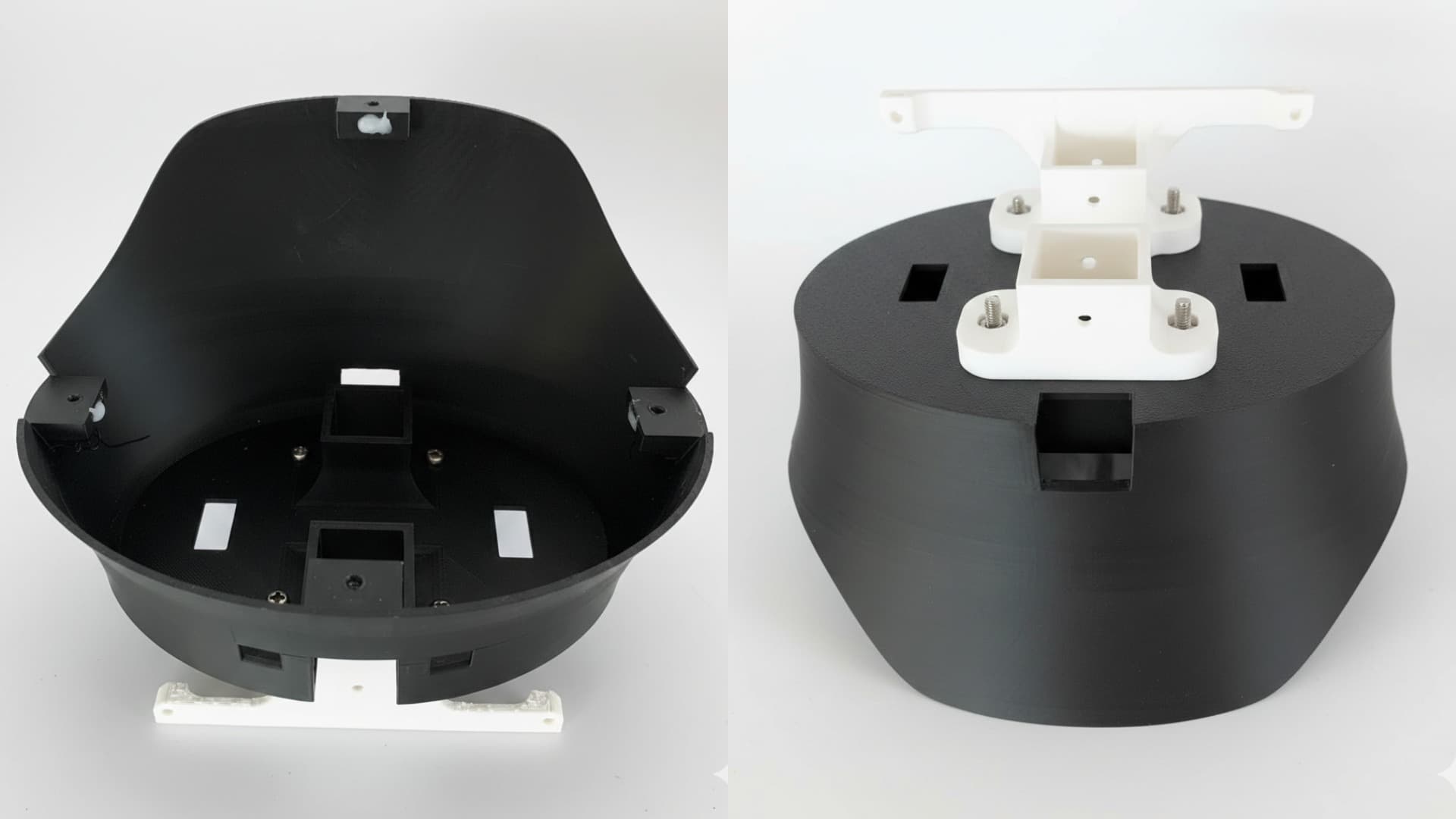
Insert M4 nuts into the designated holes as shown below and glue them if required. Repeat this process for all applicable parts.
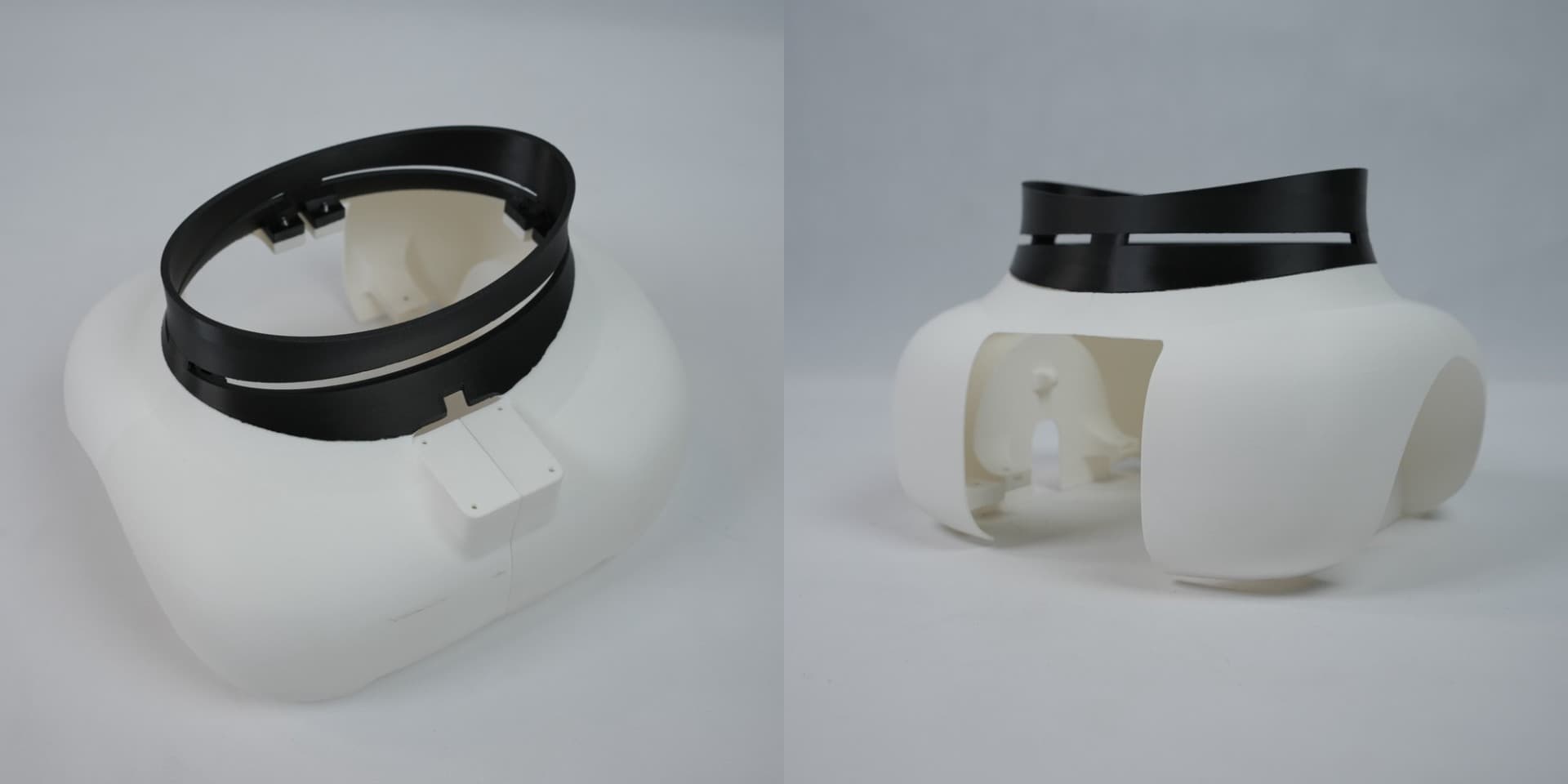
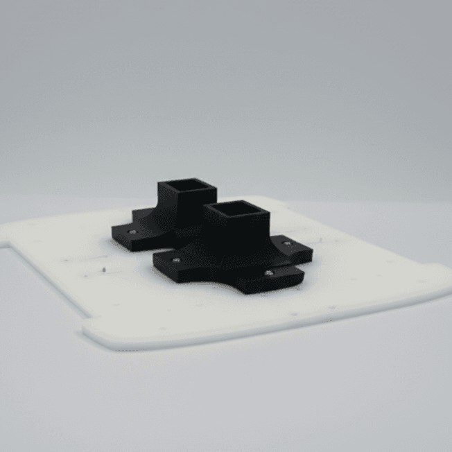
Assemble the parts as shown below to form the base structure by fixing the connecting parts properly together using cutting pliers or similar tools.
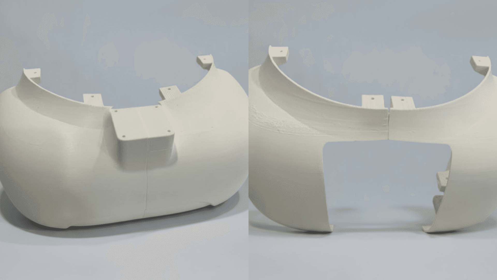
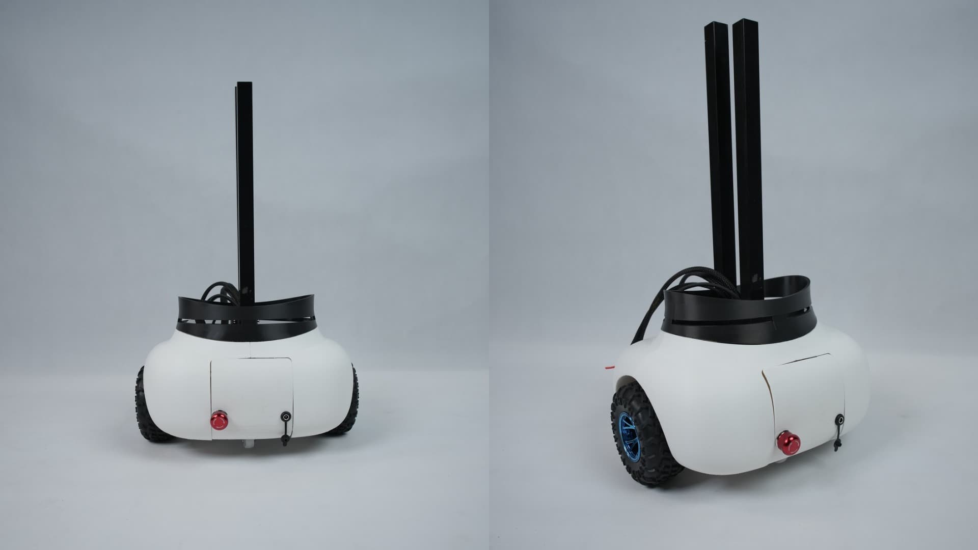
The assembled base structure should appear as shown below.
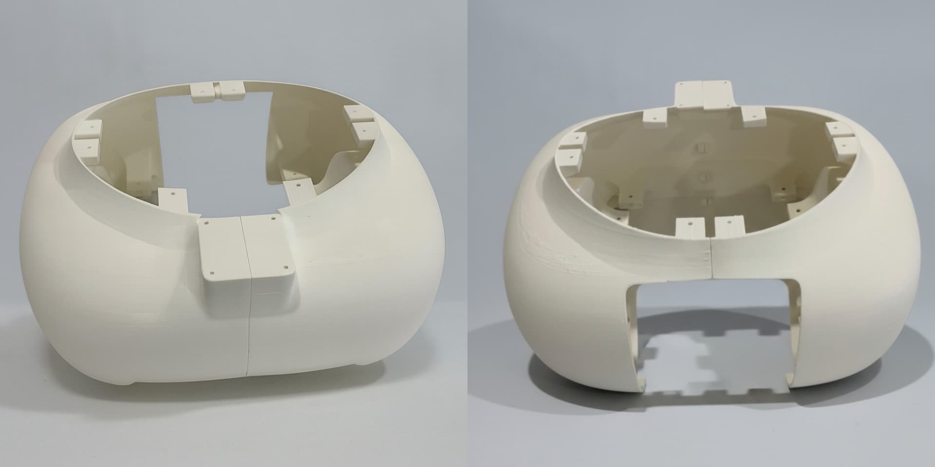
Insert 8 x M3 nuts into the Base Center Cover and secure it to the base structure using 8 x M3 bolts.
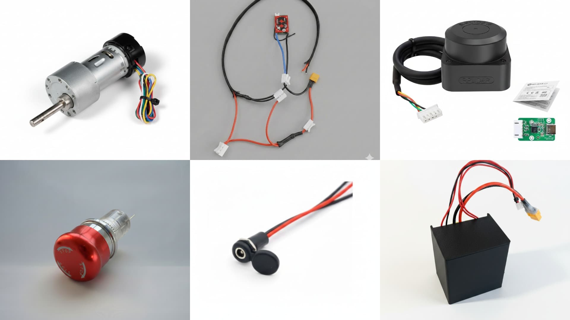
Electronic Parts
- Johnson Motor x 2
- BMS connection
- RP LiDAR
- Switch
- DC Jack (Female)
- Battery Pack
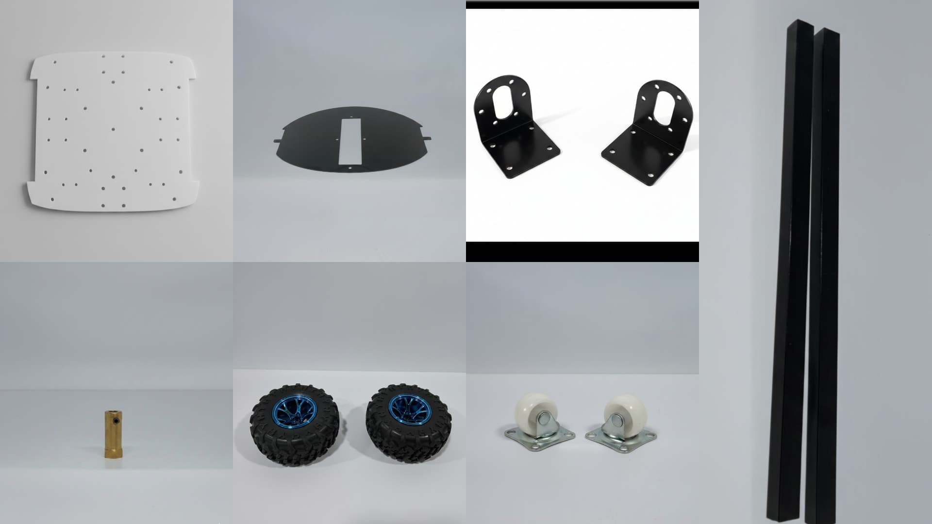
Mechanical Parts
- Base Acrylic
- BCC Acrylic
- Wheel Bracket x 2
- Coupler x 2
- Wheel x 2
- Caster Wheel x 2
- Aluminium Square Pipe x 2 (51.4 cm, 49.8 cm)
Step 2: Base Body Assembly
Secure the base joint on the base acrylic using 6 x M4 nuts and M4 bolts.
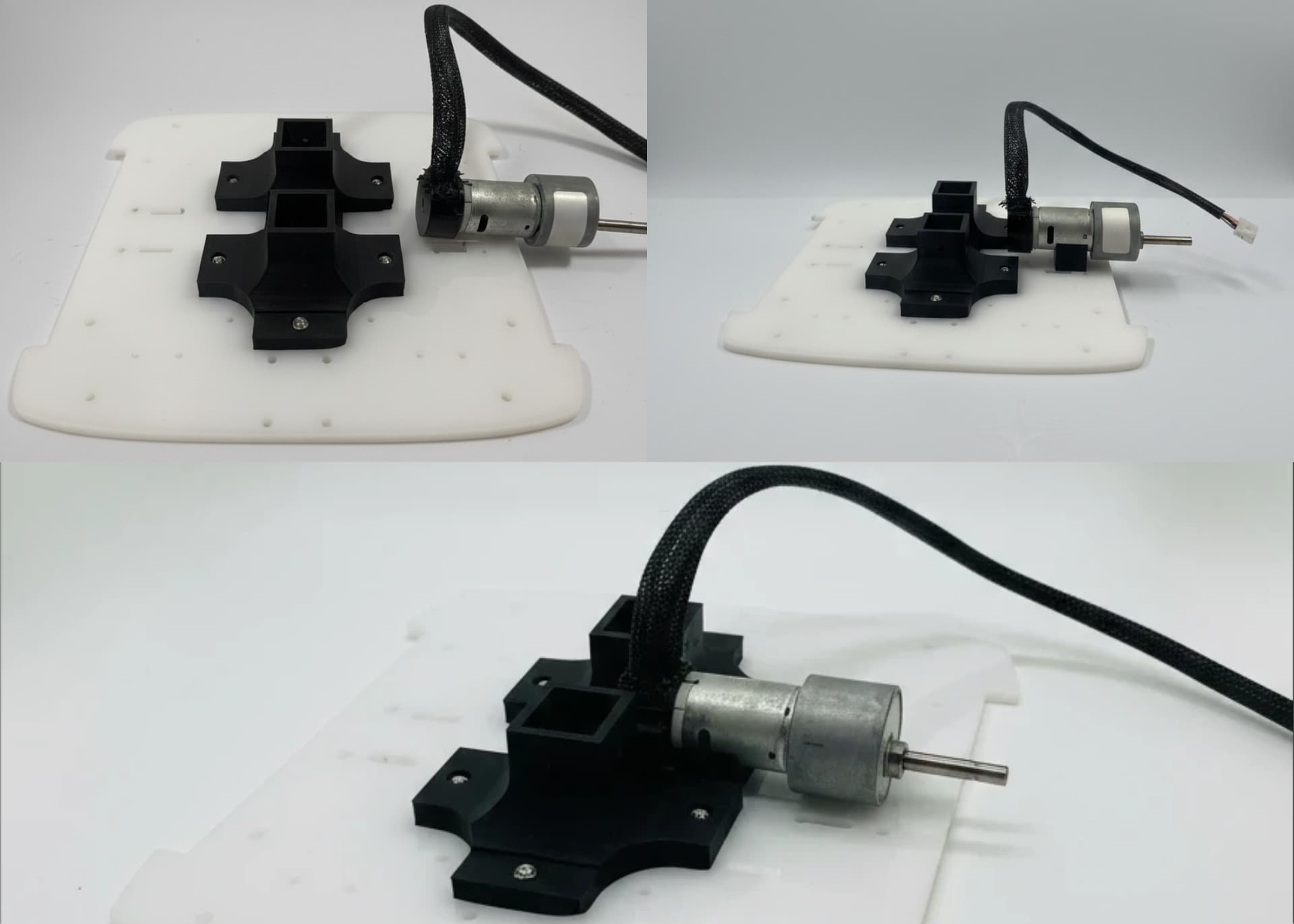
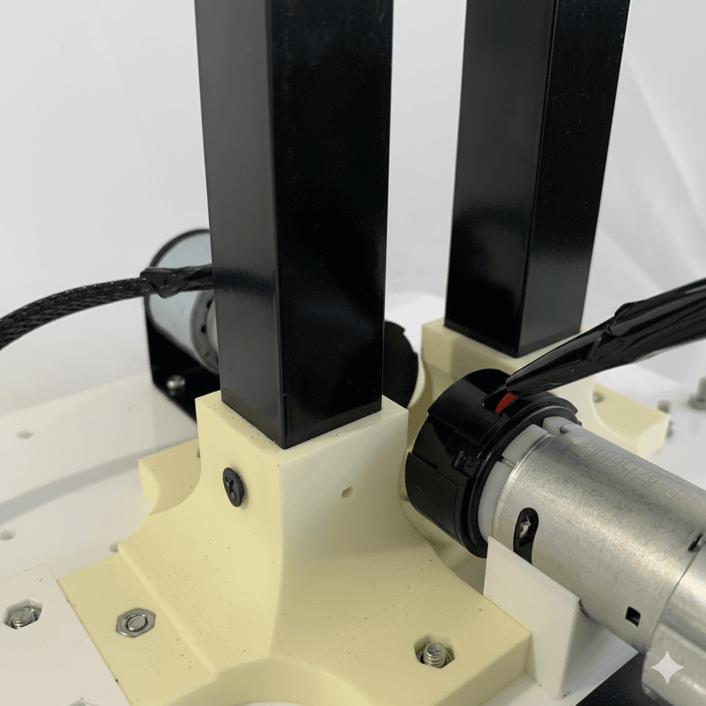
Mount the Johnson motor on the Motor Stabilizer for support and slide it into the base joint.
Install 2 x wheel brackets on the base acrylic using 4 x M4 nuts and bolts.
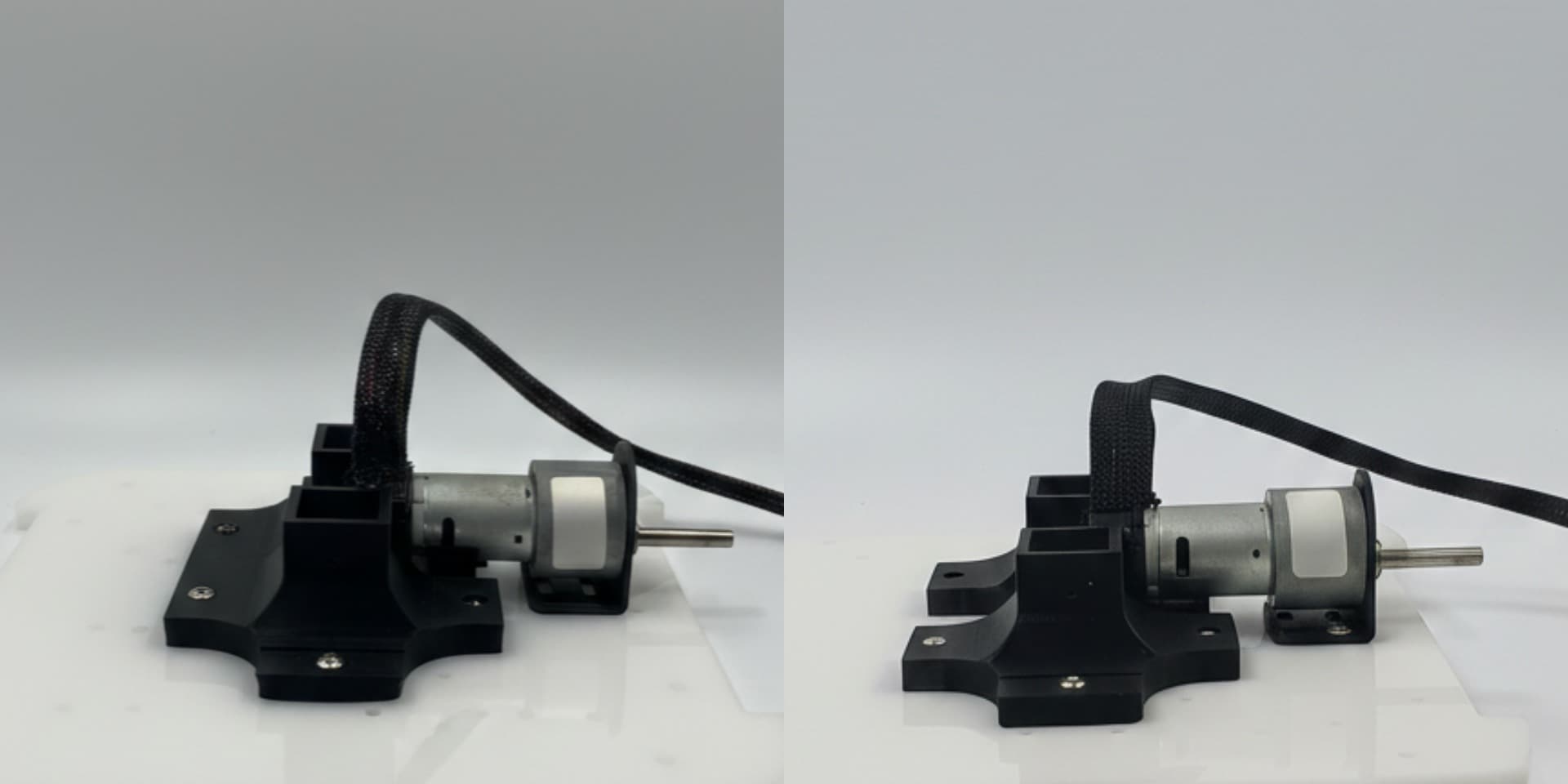
Repeat the same process for the second motor.
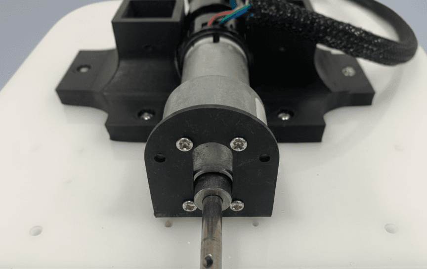
Secure the Johnson motors to the brackets using 4mm bolts.
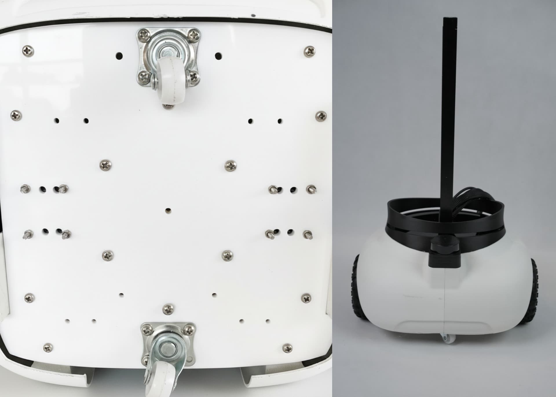
Insert 4 x M4 nuts into the battery rail and secure it to the base acrylic along with the caster wheels.
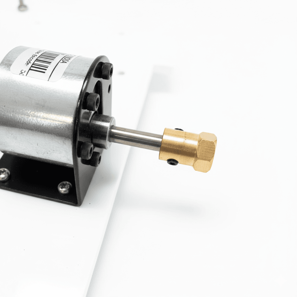
Attach 2 x couplers to the Johnson motors and tighten using an Allen key.
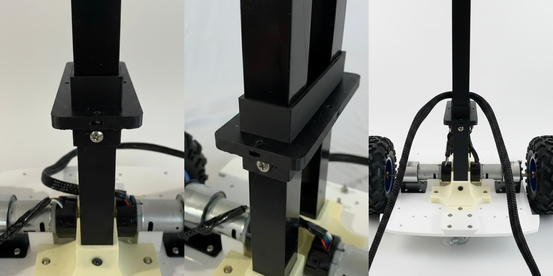
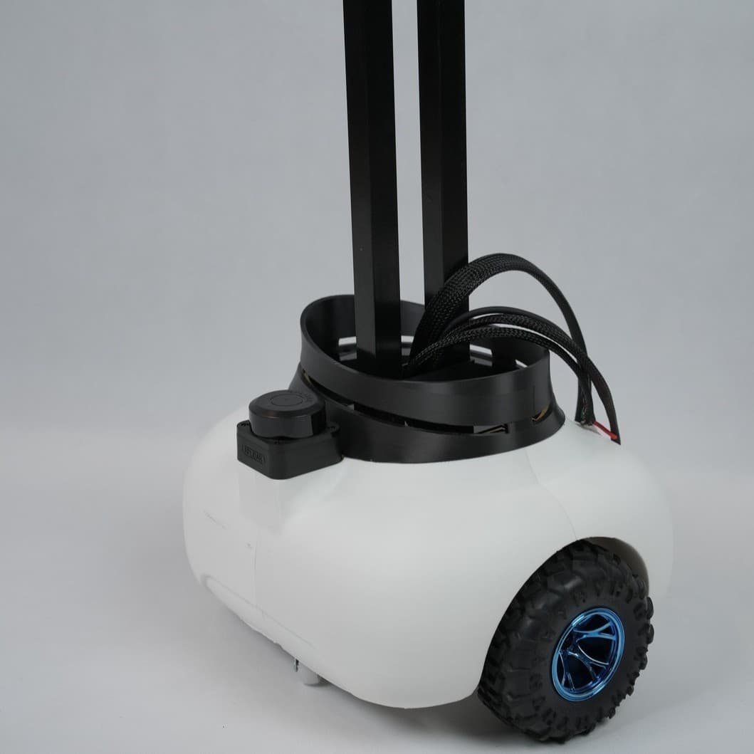
Install one 51.4 cm aluminium square pipe on the front and one 49.8 cm pipe on the rear portion of Base Joint.
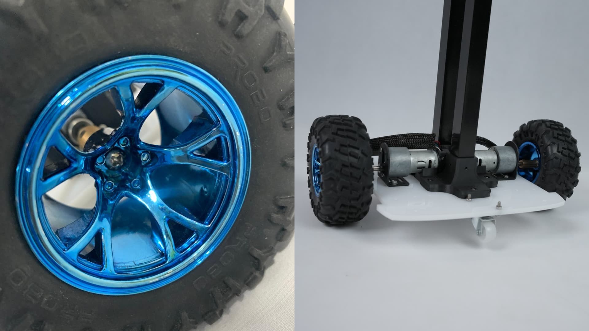
Attach 2 x wheels to the couplers using its bolts and tighten it using allen key.
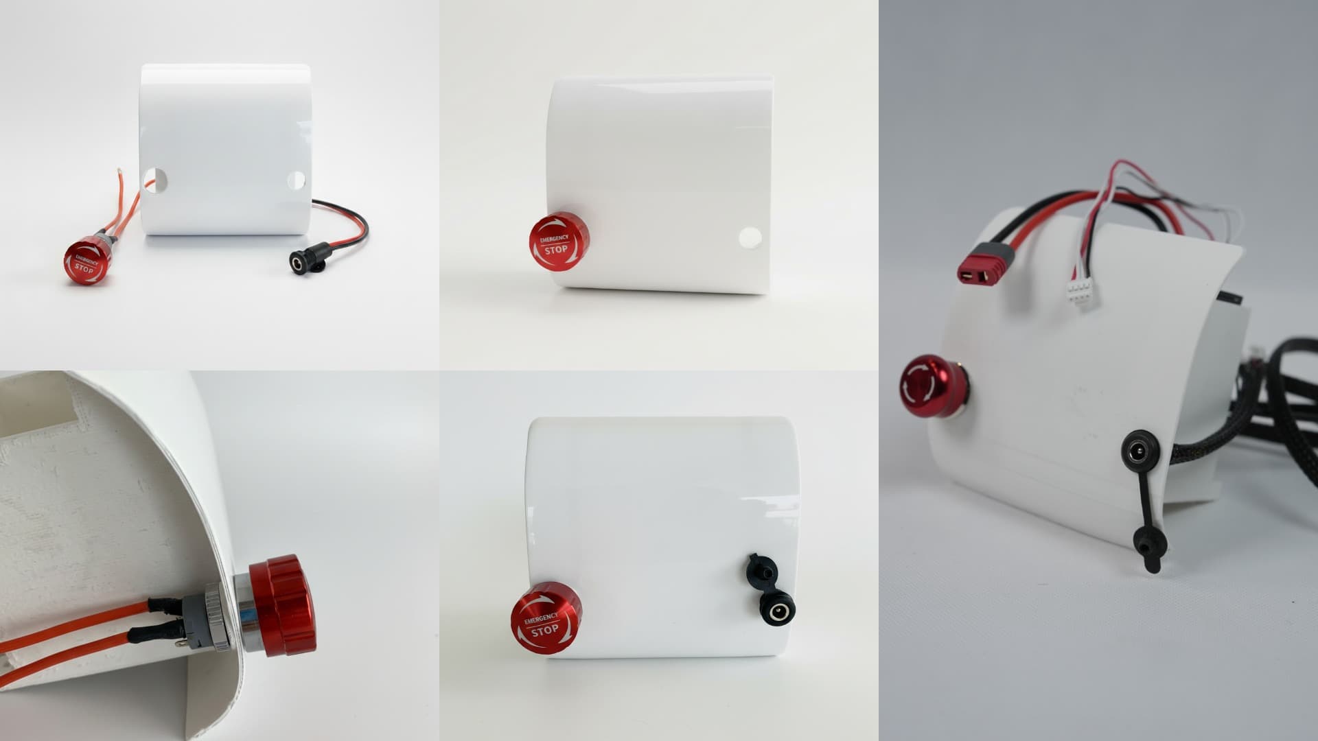
Battery Holder Setup
Install the Switch and DC jack in their respective slots and insert the BMS on the back pocket of the battery holder without damaging the wires. And then insert the battery into the Battery Holder carefully
Slide the BCC acrylic holder through the aluminium pipe and secure it in place using 2 x sharp screws by aligning its holes with holes provided on the aluminium square pipes
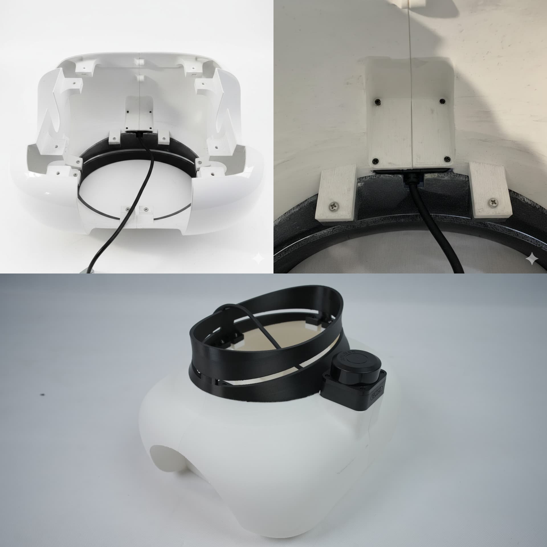
Mount the RP LiDAR sensor on the front section by screwing it from below using 4 x 2.5m bolts of size 4mm.
Secure the base portion to the base acrylic using 8 x M4 bolts on the lower part of base acrylic.
Slide the battery holder through the battery rail and secure it in place using 2 x M3 bolts on the lower part of Base Acrylic
Lower the BCC acrylic along the aluminium pipes and secure it to the holder using 4 x M3 bolts.
The base assembly is now complete.
Middle Shell Parts
Middle Lower Shell, Middle Center Shell, Middle Top Shell, Body Center Joint
Secure the Body Center Joint onto the Middle Top Shell using 4 x M4 nuts and bolts by inserting the nuts into the slots of the Body Center Joint and screwing it from below.
Assemble the Middle Lower Shell, Middle Upper Shell, and Middle Top Shell using 4 x M3 nuts and bolts.
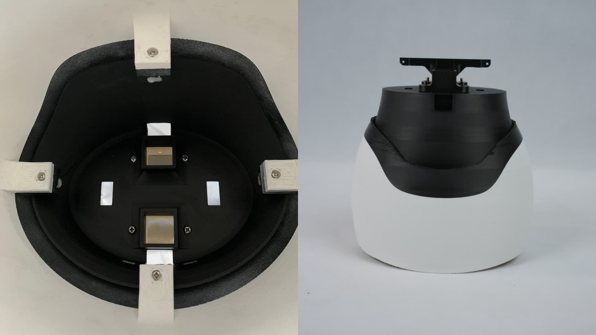
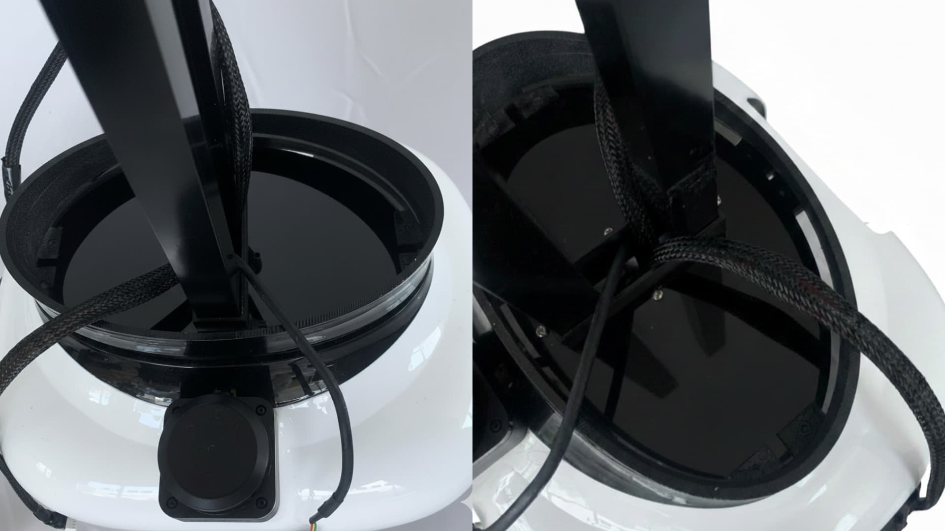
Slide the complete middle structure through the aluminium pipes onto the base of the robot. Screw the Body Center Joint to the aluminium pipe by aligning the hole on the aluminium with the joint to make it stay in place. Ensure proper routing of all wires and cables from the base to the upper body.
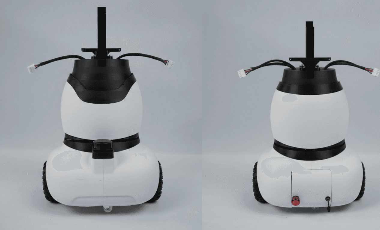
Make sure the right motor’s cable is passed through the right hole of Middle Top Shell and the left motor’s cable through the left hole.
The lower body assembly is now complete.