Electronics Assembly
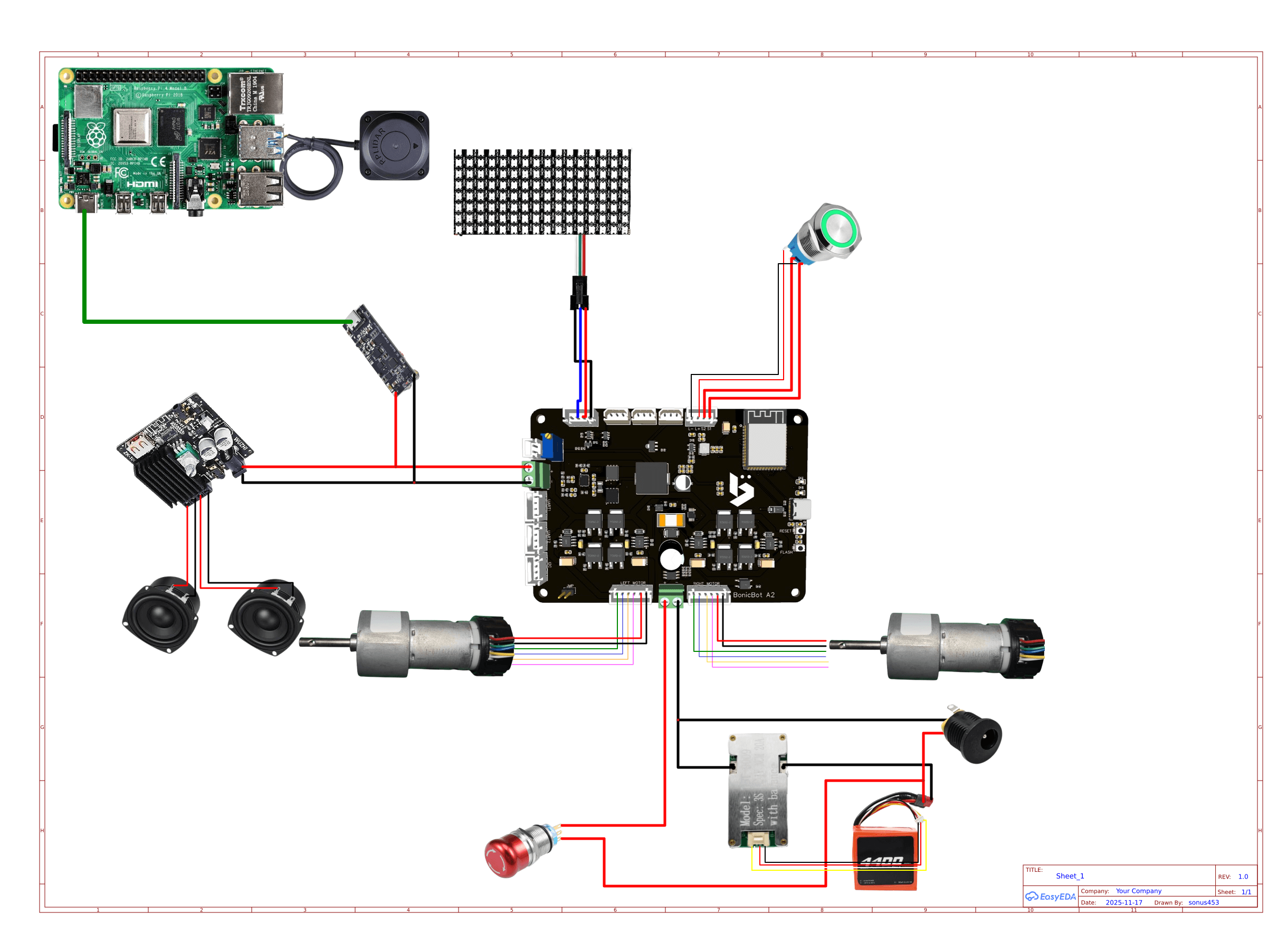
Circuit Diagram
1. Base Electronics Assembly
Step 1 — BMS & Battery Setup
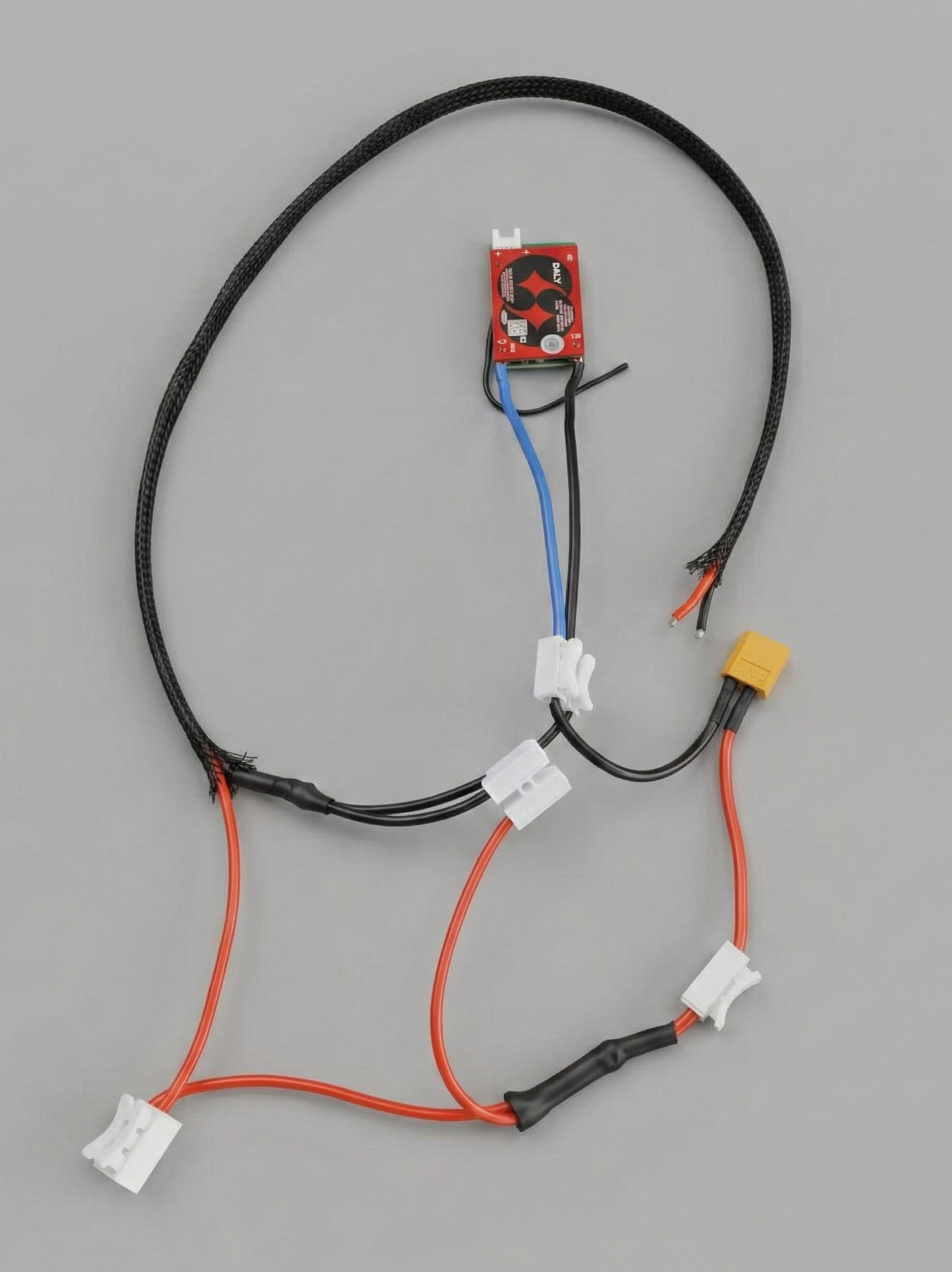
- Connect the 4-pin connector coming from the battery to the male connector on the BMS
- Connect the battery’s 2-pin nylon connector (female) to the 2-pin nylon connector (male) by ensuring the right polarity.
- Route the BMS P- wire (black) to the upper body for later connection to the Main PCB.
Step 2 — Input Supply Connection
There are two cable connectors available:
- One connector has two red wires attached.
- The other connector has one red wire and one black wire attached.
Connect the switch wires to the connector with two red wires.
Connect the DC jack (female) wires to the connector with one red and one black wire, ensuring that the correct polarity is maintained.
Step 3 — Motor Wiring
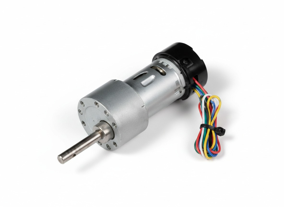
- Take the left motor 6-pin female connector and route it to the upper body.
- Take the right motor 6-pin female connector and route it to the upper body.
Step 4 — LiDAR Installation
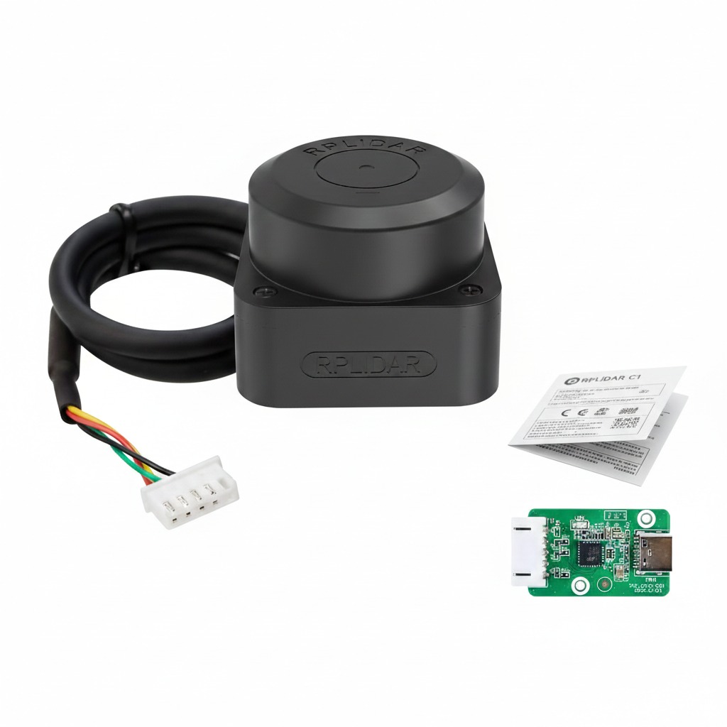
- Connect the LiDAR connector to the RP LiDAR USB adapter.
- Attach the RP LiDAR USB adapter to the aluminum mount so it stays in place.
- Connect the USB-C cable to the adapter and route it to the upper body for later connection to the Raspberry Pi.
2. Upper Body Electronics Assembly
Step 5 — Amplifier Connections
- Connect the amplifier DC jack to the amplifier input.
- Connect the red and black wires from the amplifier DC jack to the splitter IN.
- Route the red and black wires from the splitter OUT to the PCB area for later connection.
Step 6 — Speaker Wiring
- Wire with black stripe corresponds to Negative (–).
- Wire without stripe corresponds to Positive (+).
- Connect all four wires to the speaker connector, making sure the polarity is correct.
Step 7 — Charging Module
- Connect the positive and negative wires of the charging module to the splitter OUT.
- Connect a USB-C cable from the charging module to the Raspberry Pi.
- Route all module wires to the PCB area for later connection.
Step 8 — Raspberry Pi UART
- Prepare both the 4-pin female UART cable from the Raspberry Pi.
- Route the cable to the PCB area for later connection.
Step 9 — RGB LED Matrix
- Connect the matrix light connector to the 4-pin male connector.
- Route the 4-pin female connector to the PCB area for later connection.
Step 10 — Push Button
- Connect the 4-pin push button connector and route it to the PCB area for later connection.
Power
- Battery Positive → PCB 12V (+)
- BMS P- → PCB 12V (–)
- Splitter OUT → PCB power input terminals
Motors
- Left motor 6-pin → Left motor port
- Right motor 6-pin → Right motor port
Raspberry Pi UART
- PCB UART 1 → Pins No: 7 of Raspberry Pi
- PCB UART 2 → Next two pins
RGB LED Matrix
- 4-pin matrix cable → PCB Matrix Light port
Push Button
- 4-pin switch connector → PCB Switch port
Servos
- Connect all servo wires to their labeled ports on the PCB.
Speaker
- Connect amplifier output wires to the speaker connector.
LiDAR
- USB-C → Raspberry Pi USB port
4. Final Verification
- Verify all wires are securely connected.
- Ensure correct polarity for all power and speaker connections.
- Check that motors, servos, LEDs, LiDAR, and speakers are functioning correctly.
- Ensure no wires are under tension or pinched.
Electronics assembly is complete.
Last updated on