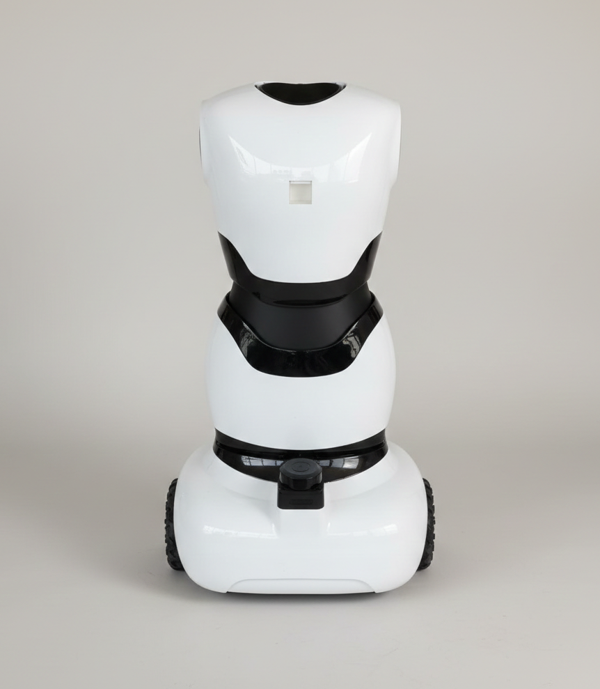
Upper Body Assembly
Step 1: Collecting All Required Parts
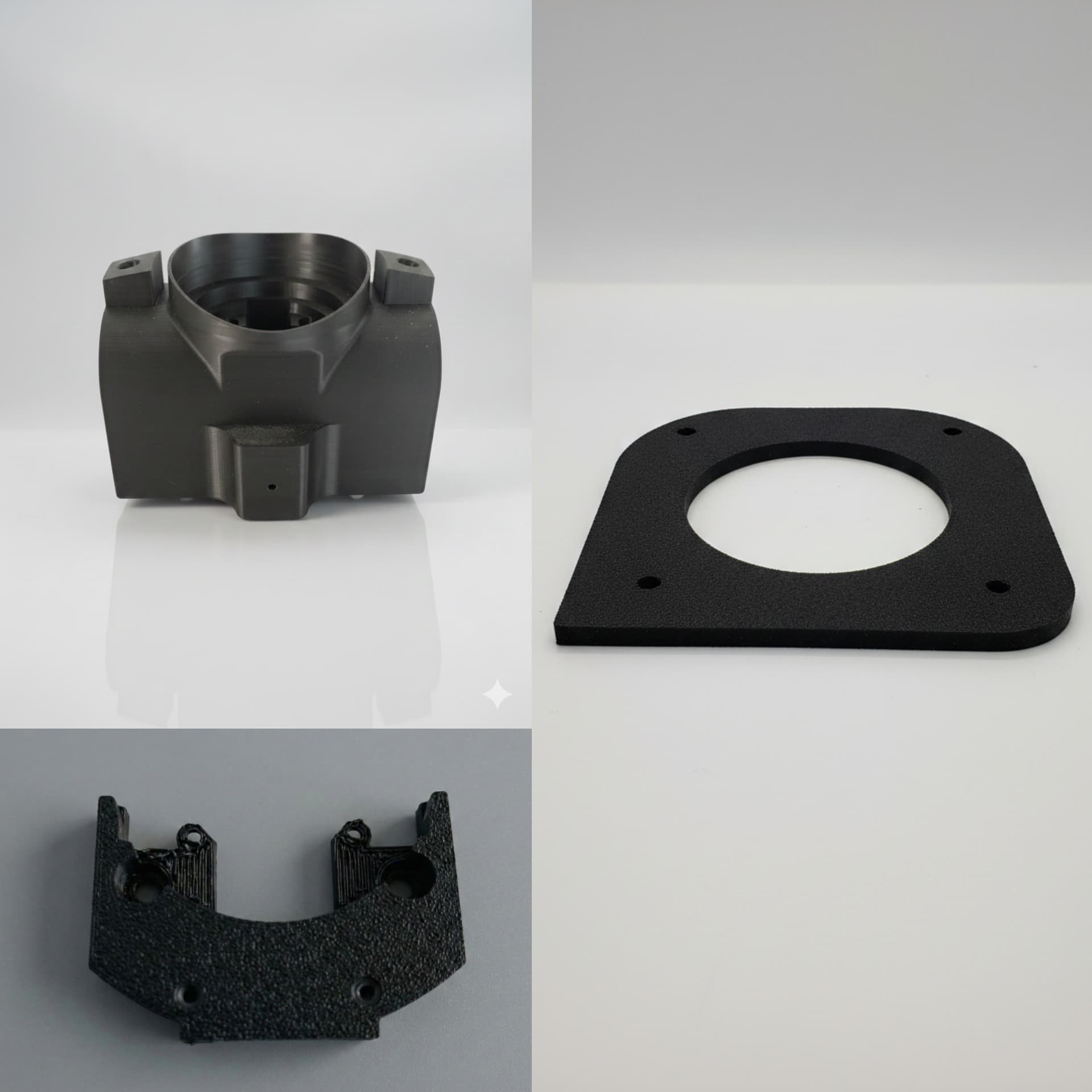
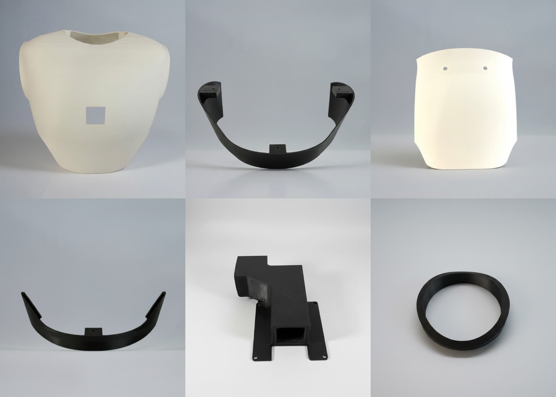
3D Printed Parts
- Center Joint
- Center Joint Cover x 2
- Center Joint Servo x 2
- Phone Mount Joint
- Neck Cover
- Upper Main Body
- Upper Front Lower
- Upper Rear Cover
- Upper Back Lower
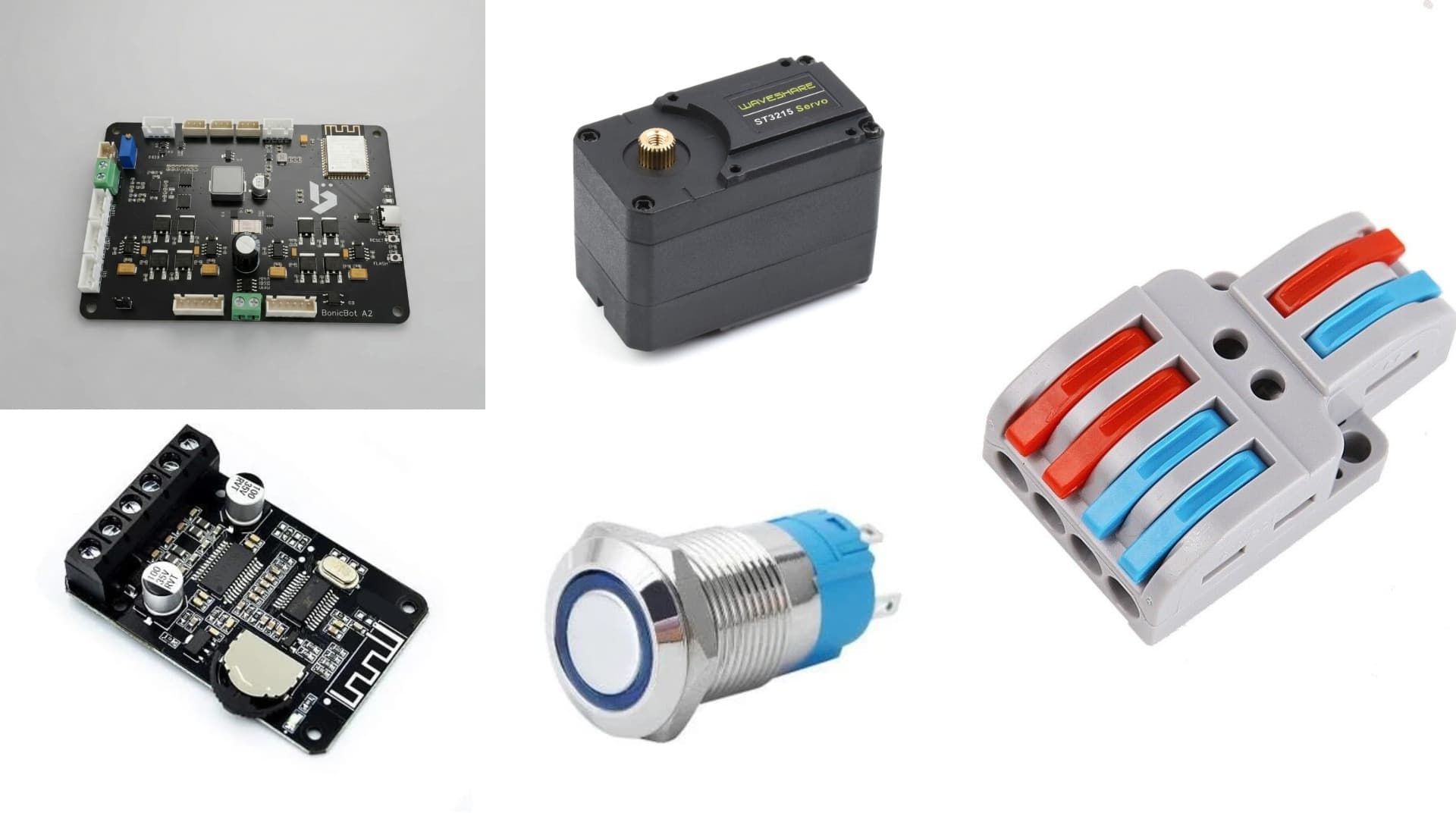
Electronic Parts:
- Main PCB
- Servo Motor x 3
- Amplifier
- Push Button
- Splitter
Mechanical Parts:-
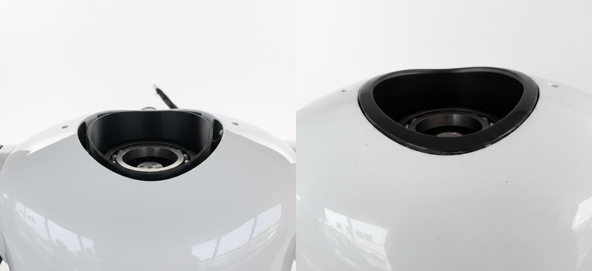
- Metal Bearing x 3
Step 2: Starting the Upper Body Assembly
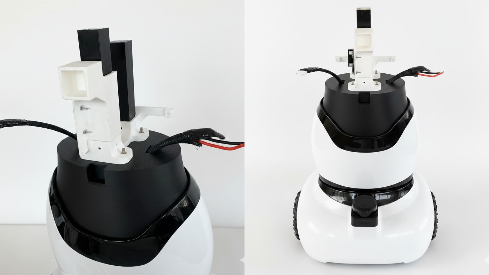
Center Joint Assembly
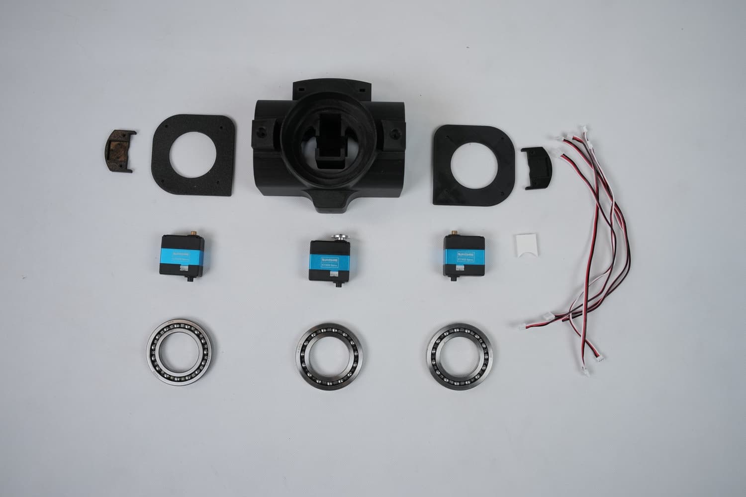
Items required:
- Metal bearing x 3
- Servo motors x 3
- M3 nut and bolt x 18
Insert M3 nuts into all the holes shown below and glue them properly to stay in place.
Screw one servo on the Center Joint Servo piece of the center joint after plugging the servo cables as shown and insert it into the hand portion of the center joint
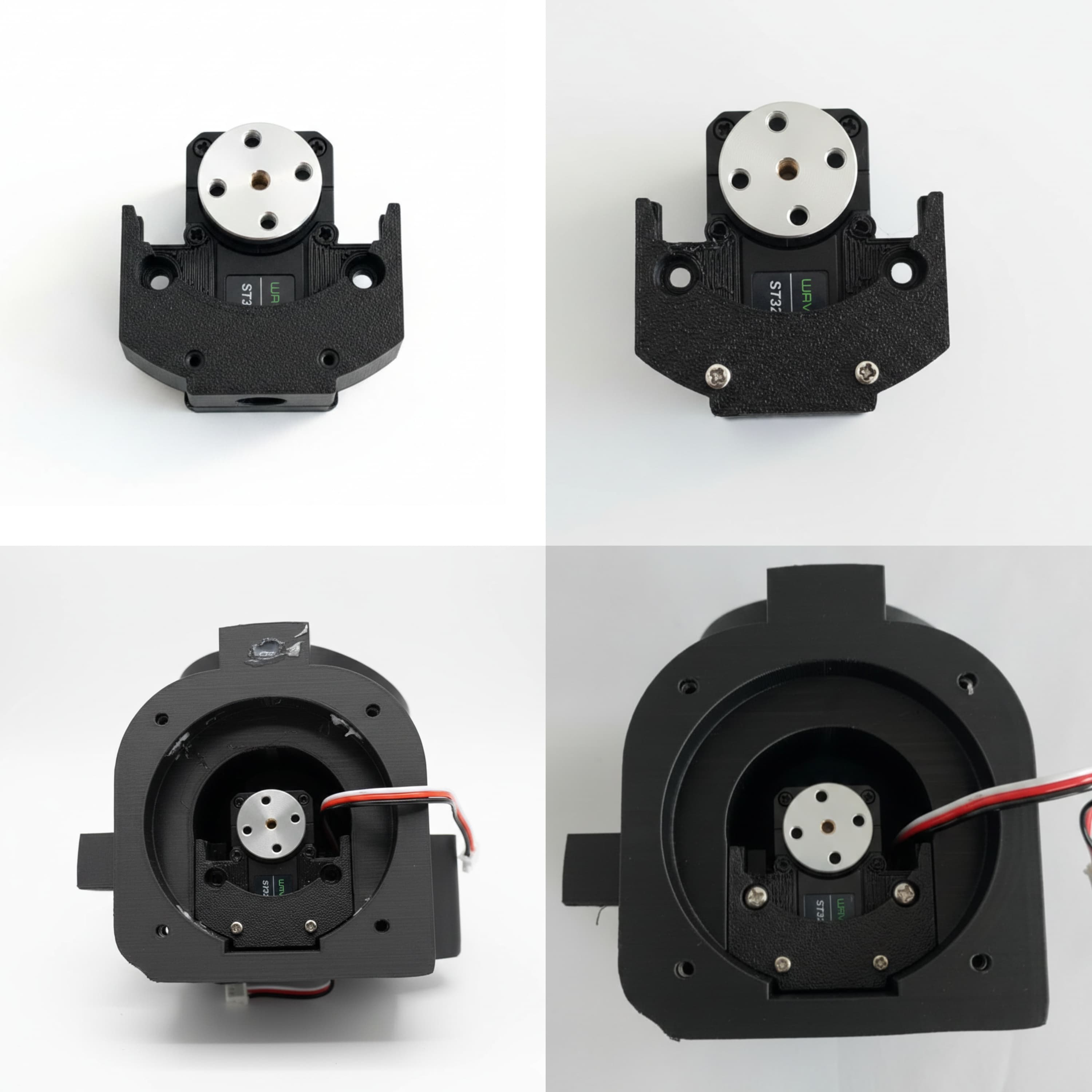
Fix a metal bearing into the hand portion as shown and seal it using Center Joint Cover piece using 4 x M3 bolts of 10mm each
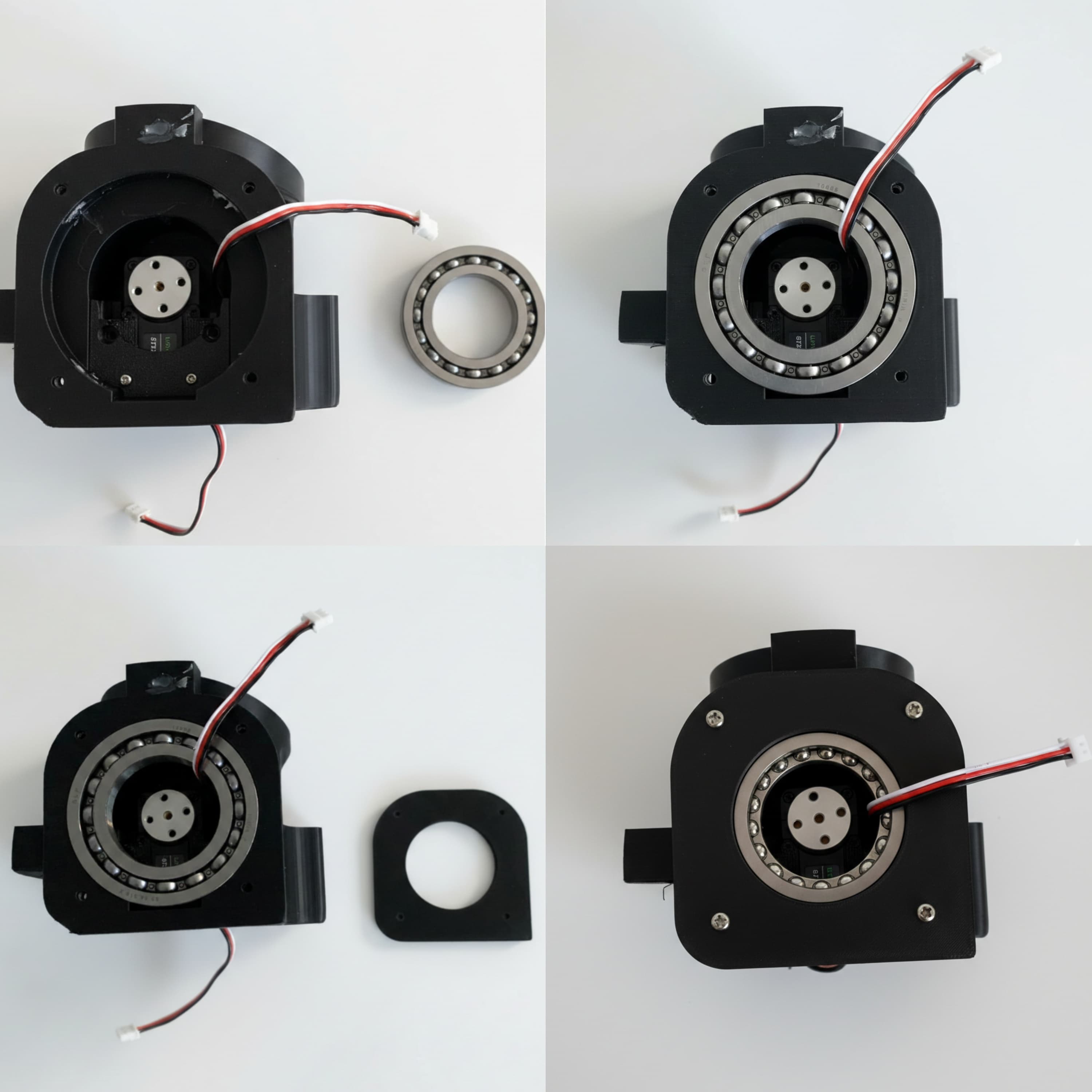
— Insert a servo motor on the head portion of Center Joint and fix a metal bearing on top. Make sure the bearings are seated properly.
The Center Joint is now assembled
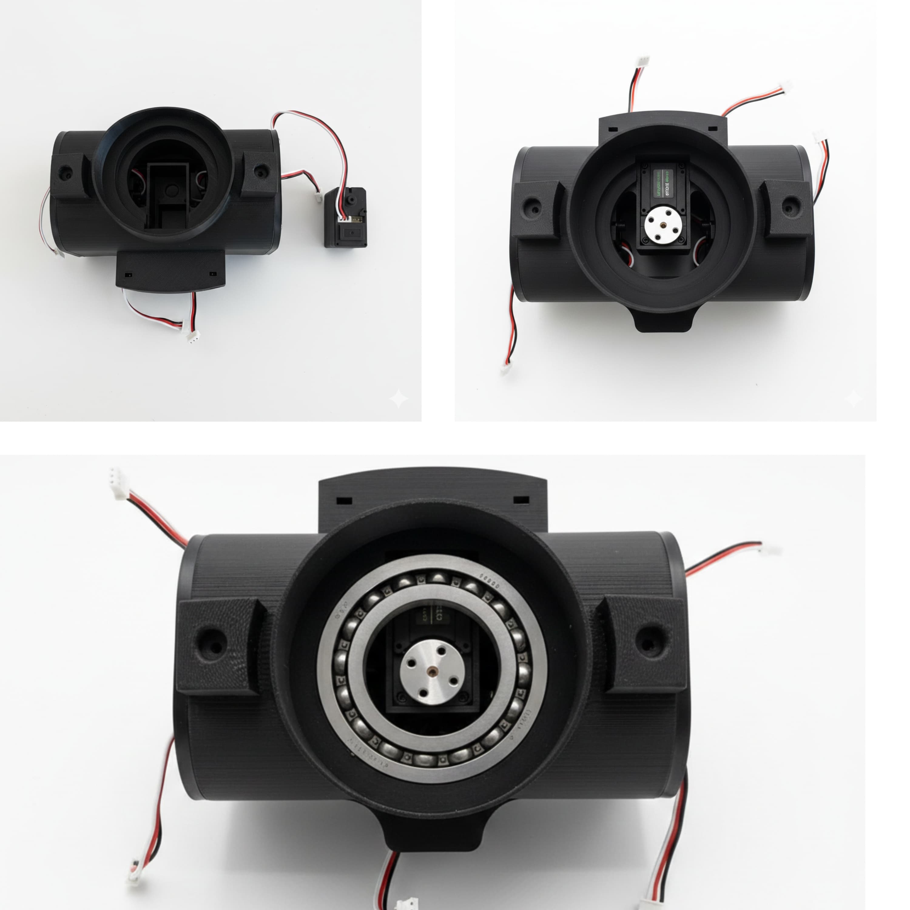
Fix the Phone Mount Joint on the front aluminium.
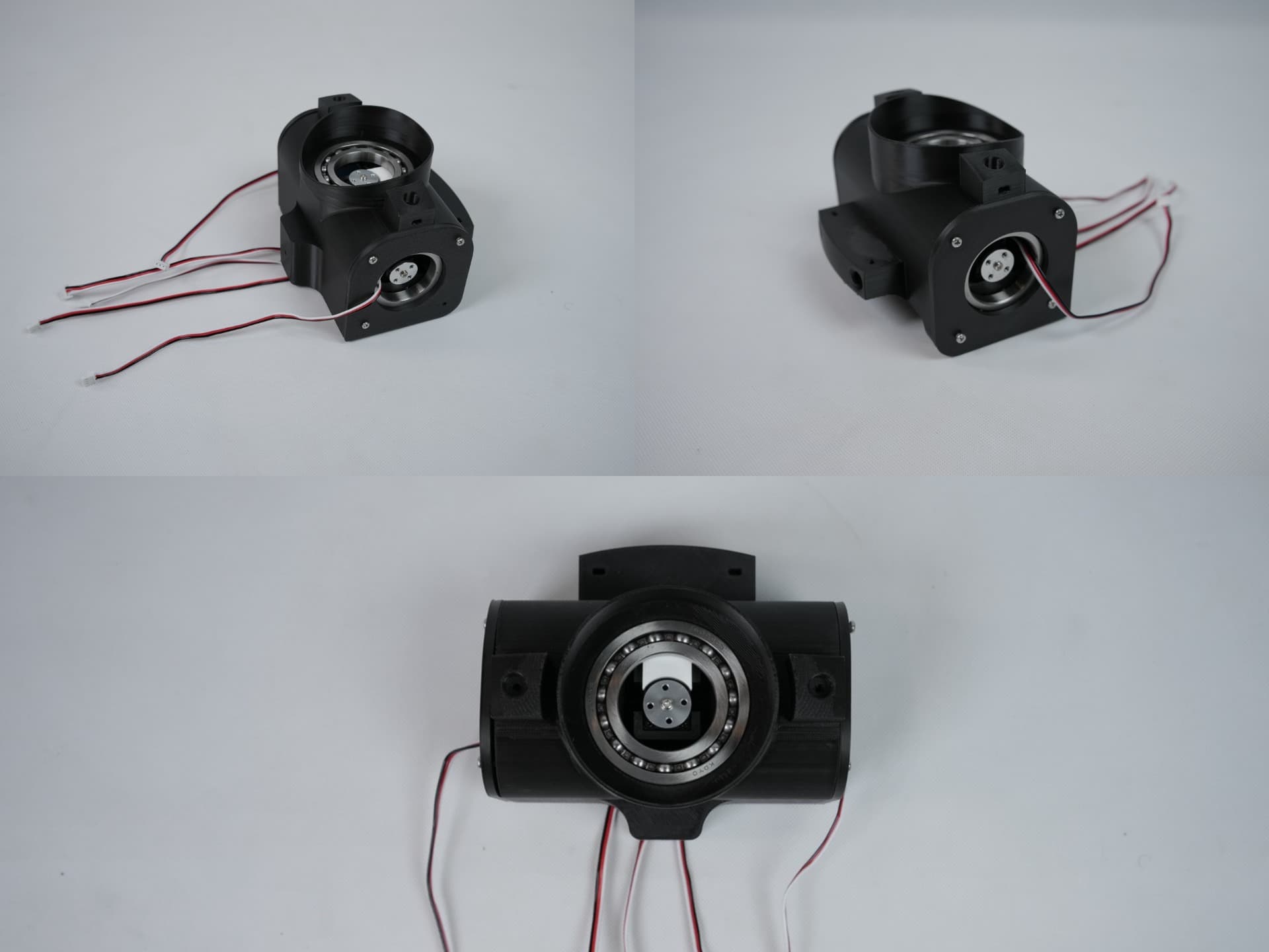
Now place the assembled Center Joint on the aluminium square pipes making sure it has been placed properly.
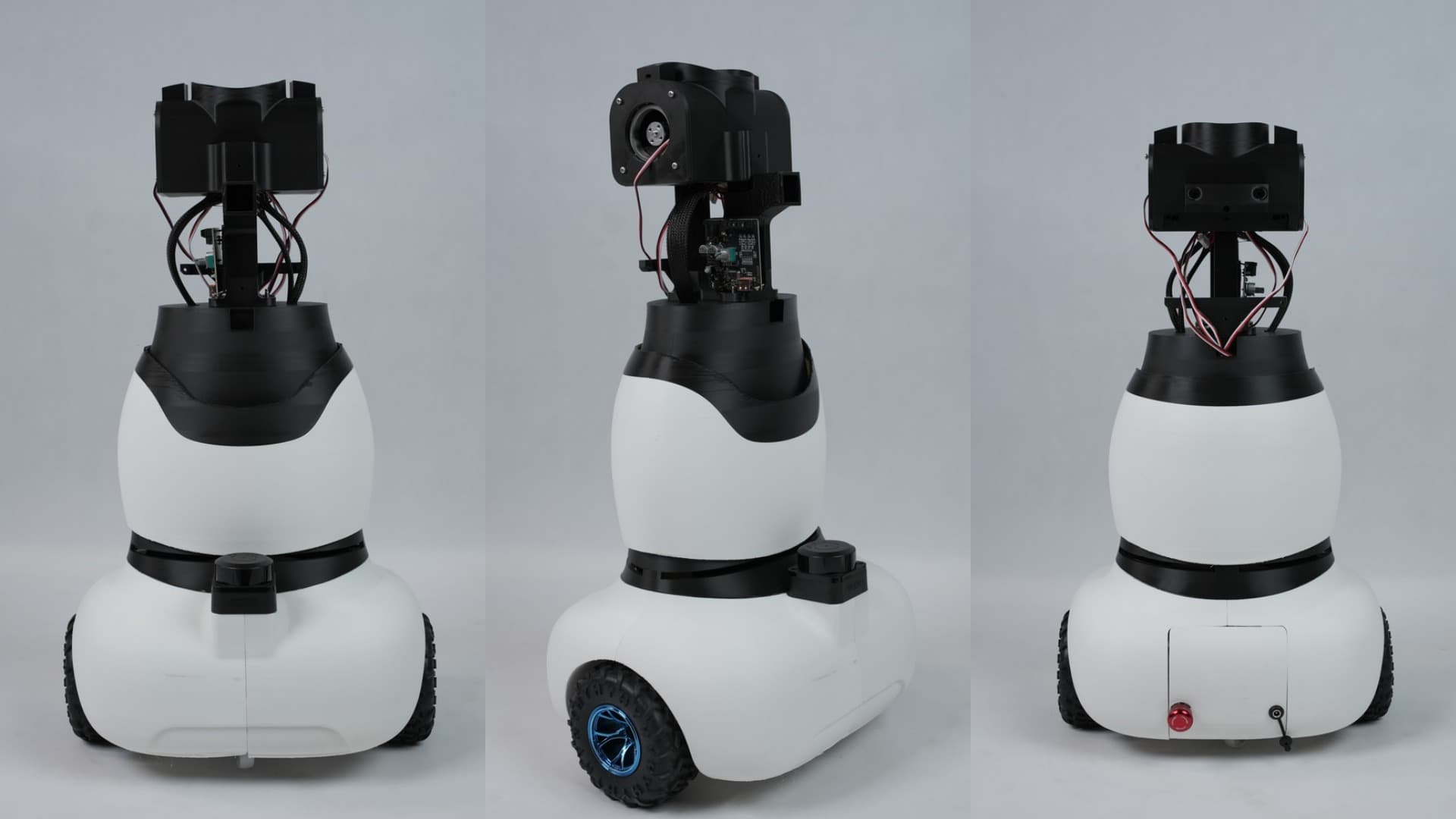
Fix the neck cover onto the center joint by aligning it properly with the Center Joint.
Now fix the upper body onto the center joint and tighten it using 2 × M3 bolts on each shoulder portions of the upper body
Now Fix the Logo Mount as shown below