Product Overview
Revolutionary Mobile Humanoid - World’s most affordable mobile humanoid robot with autonomous navigation, ROS2 compatibility, and advanced programming capabilities starting from $599.
Product Summary
Thank you for choosing BonicBot A2.
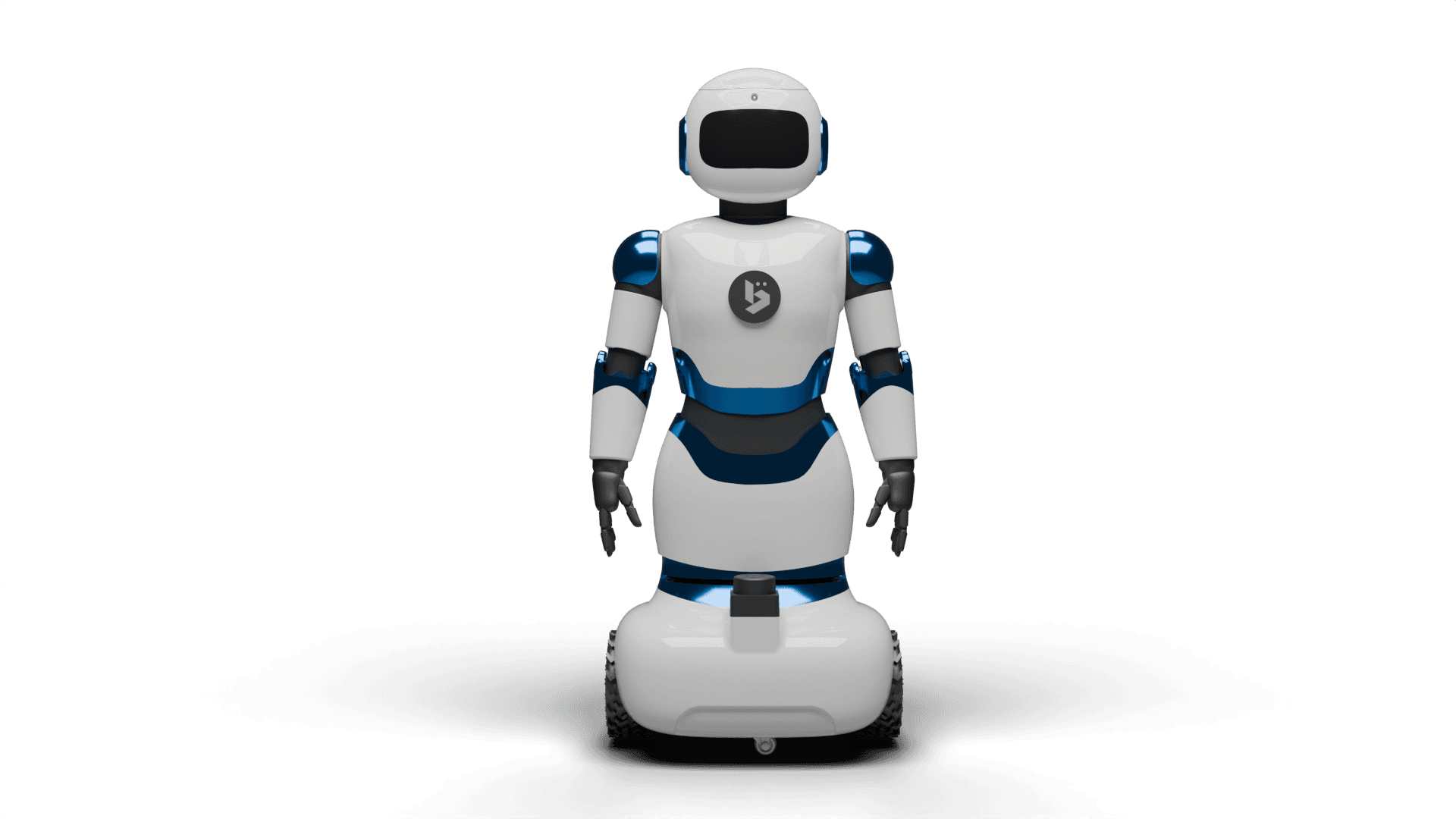
BonicBot A2 is a cutting-edge humanoid robot designed for learning, prototyping, and exploring AI. With its modular 80 cm platform featuring 3D printed parts, BonicBot A2 combines smartphone-based AI, ROS2 navigation, and real-time actuator control.
The platform enables:
- Autonomous movement
- Expressive interactions
- Programming with Python, ROS2, Blockly, or Jupyter Notebook
BonicBot A2 is ideal for hands-on robotics education, engineering labs, makerspaces, and rapid experimentation.
System Architecture
BonicBot A2 uses a hybrid compute architecture to deliver high performance:
-
Smartphone
- AI processing
- Camera-based vision
- Face display
- App-based control
-
Raspberry Pi CM4
- ROS2
- SLAM and navigation
- Sensor fusion
-
ESP32
- Real-time motor control
- Servo control
- micro-ROS
This layered design ensures smooth navigation, responsive movement, and clean separation of responsibilities for software development.
The hardware is modular, with upgrade paths for arms, grippers, and additional accessories.
Specifications
Hardware Specifications
| Category | Specification |
|---|---|
| Height | 80 cm |
| Weight | ~6.5 kg |
| Degrees of Freedom | 7 DOF (expandable to 11 with add-on arms) |
| Compute | Raspberry Pi 4 (8 GB) + Smartphone (MediaTek Dimensity 7300) |
| Navigation | LiDAR + SLAM Toolbox + Nav2 (ROS) |
| Display | RGB LED Matrix (expressive face) |
| Battery | 4,400 mAh |
| Connectivity | Wi-Fi 6, Bluetooth 5.3 |
| Material | 3D-printed chassis, modular frame |
Software Specifications
| Component | Specification |
|---|---|
| Operating Framework | ROS2 |
| Navigation | SLAM, mapping, path planning, waypoint navigation |
| AI Integration | Smartphone-based AI, VLM support |
| Programming | Python SDK, Blockly, Jupyter Notebook, ROS2 |
| Simulation | Gazebo support |
| Cloud Platform | Remote control, monitoring, multi-robot management |
Key Features
Autonomous Navigation
- LiDAR-based mapping and localisation
- Nav2-based autonomous path planning
- Real-time obstacle detection and avoidance
- Ability to save and reuse custom maps
Multi-Environment Programming Support
BonicBot A2 supports four main development environments:
-
Python SDK
High-level API for scripting behaviours and automation. -
ROS2
Full robotics stack for SLAM, navigation, and research workflows. -
Blockly
Drag-and-drop visual programming for beginners and classroom use. -
Jupyter Notebook
Interactive coding environment for lessons, experiments, and demos.
Smartphone-Powered AI
- On-device AI, using smartphone compute
- Camera-based vision features
- Multi-language voice interaction
- LED facial expression control
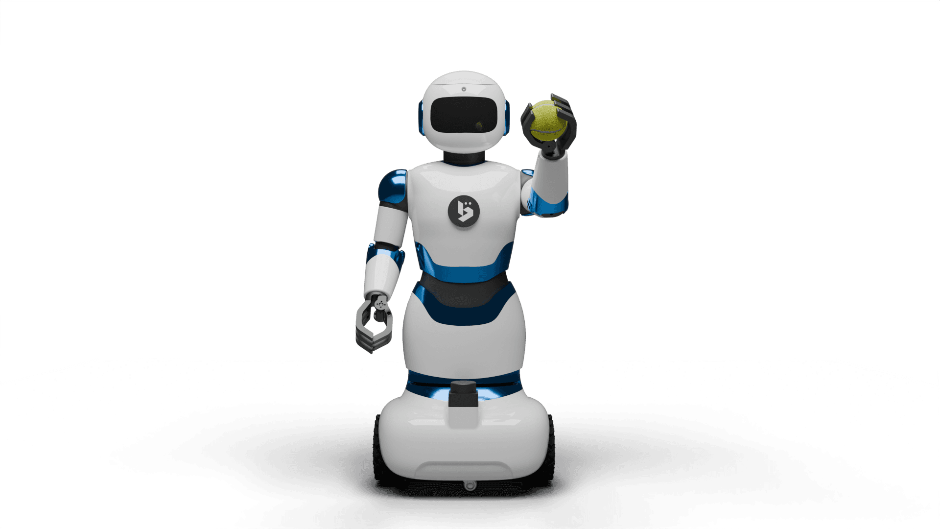
Modular Design
- Plug-and-play arms
- Grippers and holders
- Expansion points for add-ons and accessories
Cloud Connectivity
- Remote robot control
- Parameter monitoring and diagnostics
- Fleet management capabilities
- Over-the-air updates
Educational & Research Ready
- Suitable for robotics courses and workshops
- Ideal for engineering labs and makerspaces
- Compatible with ROS tools, Gazebo, and Python-based workflows
Tier-wise Product Variants
BonicBot A2 is available in two main configurations:
- Fully Finished Robot (Premium Tier)
- Ready-to-Assemble Kit (RTA Kit)
1. Fully Finished Robot (Premium Tier)
The Fully Finished Robot is a ready-to-use BonicBot A2 that arrives:
- Completely assembled
- Calibrated
- Factory tested
All essential electronics, mechanical parts, and internal wiring are pre-installed.
Package Contents (Included)
| Sl No | Components | Quantity |
|---|---|---|
| 1 | Fully Finished Robot | 1 |
| 2 | Power Adapter / Charger | 1 |
| 3 | Protective Carry Case | 1 |
| 4 | Documentation / Quick Start Guide | 1 |
| 5 | Warranty | 1 Year |
Add-ons (Optional Accessories)
| Sl No | Components | Quantity |
|---|---|---|
| 1 | Remote (Joystick) | 1 |
| 2 | Gripper | 1 pair |
| 3 | Utility Plate | 1 pair |
To get started, go to this link: Start Usage
2. Ready-to-Assemble Kit (RTA Kit)
The Ready-to-Assemble (RTA) Kit provides:
- All electronics and mechanical parts
- All 3D printed parts
The user performs the mechanical assembly and final integration.
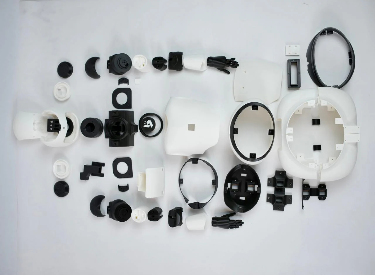
2.1 3D Printed Parts
| Sl No | Components | Quantity |
|---|---|---|
| 1 | BaseFrontLeft | 1 |
| 2 | BaseFrontRight | 1 |
| 3 | BaseRearLeft | 1 |
| 4 | BaseRearRight | 1 |
| 5 | BaseCenterCover | 1 |
| 6 | BatteryHolder | 1 |
| 7 | BaseAcrylicHolder | 1 |
| 8 | BaseJoint | 1 |
| 9 | MotorStabilizer | 2 |
| 10 | BatteryRail | 1 |
| 11 | BaseLowerShell | 1 |
| 12 | BaseCenterShell | 1 |
| 13 | BaseTopShell | 1 |
| 14 | UpperFrontLower | 1 |
| 15 | UpperBackLower | 1 |
| 16 | UpperMainBody | 1 |
| 17 | UpperRearCover | 1 |
| 18 | NeckCover | 1 |
| 19 | CenterJoint | 1 |
| 20 | CenterJointServoLeft | 1 |
| 21 | CenterJointServoRight | 1 |
| 22 | CenterJointCoverRight | 1 |
| 23 | CenterJointCoverLeft | 1 |
| 24 | ServoClamp | 1 |
| 25 | PhoneMountJoint | 1 |
| 26 | BodyCenterJoint | 1 |
| 27 | NeckJoint | 1 |
| 28 | LogoMount | 1 |
| 29 | Face | 1 |
| 30 | HeadCover | 1 |
| 31 | SpeakerHolderLeft | 1 |
| 32 | SpeakerHolderRight | 1 |
| 33 | EarRight | 1 |
| 34 | EarLeft | 1 |
| 35 | RPiHolder | 1 |
| 36 | ShoulderJointLeft | 1 |
| 37 | ShoulderCoverLeft | 1 |
| 38 | UpperArmLeft | 1 |
| 39 | ElbowServoMountLeft | 1 |
| 40 | ElbowJointLeft | 1 |
| 41 | WristJointLeft | 1 |
| 42 | PalmLeft | 1 |
| 43 | ShoulderJointRight | 1 |
| 44 | ShoulderCoverRight | 1 |
| 45 | UpperArmRight | 1 |
| 46 | ElbowServoMountRight | 1 |
| 47 | ElbowJointRight | 1 |
| 48 | WristJointRight | 1 |
| 49 | PalmRight | 1 |
2.2 Electronic Components
The following electronic and mechanical components are provided.
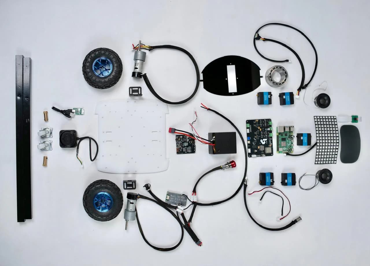
Electronics
| Sl No | Components | Quantity |
|---|---|---|
| 1 | Johnson Motor | 2 |
| 2 | BMS (Battery Management System) | 1 |
| 3 | RP LiDAR | 1 |
| 4 | RP LiDAR USB Adapter | 1 |
| 5 | Switch | 1 |
| 6 | Battery Connector | 1 |
| 7 | DC Jack (Female) | 1 |
| 8 | Battery | 1 |
| 9 | Main PCB | 1 |
| 10 | Wire Splitter | 1 |
| 11 | Amplifier | 1 |
| 12 | Servo Motor | 5 |
| 13 | RGB LED Matrix | 1 |
| 14 | Raspberry Pi Camera Module | 1 |
| 15 | Speaker | 2 |
| 16 | Raspberry Pi | 1 |
| 17 | Charging Module | 1 |
| 18 | Push Button | 1 |
| 19 | Charger | 1 |
| 20 | Cable Connector | 4 |
| 21 | Matrix Light Connector | 1 |
| 22 | Raspberry Pi 2 pin Female Header | 1 |
2.3 Mechanical Parts
| Sl No | Components | Quantity |
|---|---|---|
| 1 | Bearing | 3 |
| 2 | Display Acrylic | 1 |
| 3 | Base Acrylic | 1 |
| 4 | BCC Acrylic | 1 |
| 5 | Coupler | 2 |
| 6 | Wheel Bracket | 2 |
| 7 | Wheel | 2 |
| 8 | Caster Wheel | 2 |
| 9 | Aluminium Square Pipe (51.4 cm, 49.8 cm) | 2 |
To get the Assembly Guide, go to this link: Assembly